Fan connection with Regulator:
This diagram shows how to connect the Fan connection with the regulator. We know a regulator can control a fan's speed very easily. A regulator is a good electric device that controls a fan's speed and makes it easy to use a fan. In this diagram, we try to describe how to connect 2 fans with 2 switches and 2 regulators very easily. For a more clear description please check our youtube video to learn easily how to connect the regulator to the fan.
Diagram of Fan connection with Regulator wiring:
Components Need for this Project:
You can get the components from any of the sites below:
$ads={1}
Read Also:
Components used to make the Fan connection with Regulator:
01. Ceiling Fan
 |
| Fig 2: Ceiling Fan |
02. Switch
 |
| Fig 3: Switch |
03. Fan Regulator
 |
| Fig 4: Fan Regulator |
Thank You for visiting the website. Keep visiting for more Updates.
Frequently Asked Questions
A series of connections implies the resistance is in line with the fan. This reduces the voltage drop across the fan or its speed to your desired level. The greater the resistance, the higher the voltage drop across it, and that lowers the speed of the fan.
The regulator controls the speed of the fan, it is also meant to be the speed controller of the fan. It actually controls the voltage across the fan, so with this, we could slow down the fan or speed up the fan as we want.
The basic mechanism of an electric regulator includes the presence of resistors to reduce the voltage of the ceiling of the fan. The downside of this type of regulator is that it heats up while controlling the voltage and hence, no electricity is saved by decreasing its speed.
In summary, the advantages of using an electronic fan regulator include precise control, durability, or additional features, while the disadvantages include higher upfront cost, complexity of installation, or susceptibility to electrical issues.
You can add a resistor, a capacitor, and an inductor in series with a fan permanently. This would increase overall impedance and reduce the current flow, thus reducing the fan speed. Another possibility is to change the capacitor in auxiliary winding from 2.25 mfd to say 1.85 and 2 mfd. This will reduce the fan the speed.
You may like these posts

a light holder, and a switch. If you want to see this circuit

In this circuit first, we need to input power DP MCB then DP MCB

( Double Pole Miniature Circuit Breaker ), a single-phase energy,

This diagram shows how to make ring socket outlets diagram.

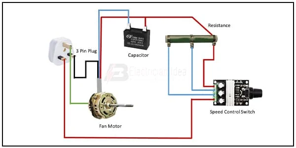
In this circuit diagram, we use a 3-Pin plug, a capacitor,

the timer and then from the timer to the light.


Post a Comment
Do leave your comments