Star Delta Timer Diagram:
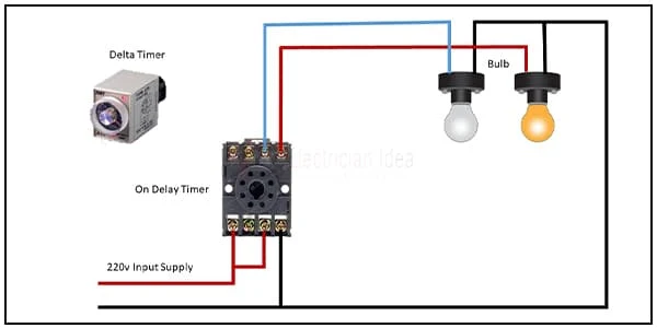
This circuit diagram shows how to connect the star delta timer diagram. In this circuit, we use a delta timer and two lights. Here we need to input power into the timer and then from the timer to the light. If you want to see this diagram animation video please check our youtube video at the below link.
Diagram of Star Delta Timer wiring:
Components Need for this Project:
You can get the components from any of the sites below:
Read Also:
Components used to make the Star Delta Timer Diagram:
01. Delta Timer
 |
| Fig 2: Delta Timer |
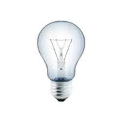
02. Light
 |
| Fig 3: Light |
Frequently Asked Questions
Set the timer to the time recorded on the stopwatch. In star Delta usually, we consider that the load or motor torque are equal when the motor reaches 75-85% of the speed. At this time you stop the star connection to go with the delta connection, the time is around 30 to 50 milliseconds, to avoid short-circuit diagram.
Star delta starters are another device that may be used to reduce current flow demand during motor startup. It is often used for starting 3-phase induction motors, but could only be used when starting the motor without load and when the required starting current flow is relatively low.
For the star connection, you just need to connect the lower ends of the windings U2, V2, or W2 together. If you then connect U1 to W2, V1 to U2, or W1 to V1, the winding connection will be in delta.
If all the branches of the resistances of the star network are equal to R then each branch in its equivalent of the delta network is equal to 3 R. If all the branches of the resistances of the delta network are equal to R then each branch in its equivalent of the star network is equal to R/3.
In a star-delta starter, 2- timers are used to control the switching of the motor windings from the star configuration to the delta configuration. The first timer is used to initially start the motor in the star configuration, which reduces the starting current flow.


Post a Comment
Do leave your comments