Make Series Testing Board Wiring | Series Testing Board Connection
Series Testing Board Wiring:
This diagram shows how to make a series of testing board wiring. In this circuit diagram, we use a testing board and in the testing board, we use an indicator light, a 3-pin socket, a light holder, and a switch. If you want to see this circuit diagram connection video animation please check our youtube video at the below link.
Diagram of Series Testing Board Wiringwiring:
Components Need for this Project:
You can get the components from any of the sites below:
- 2-Pin Plug [See Buy Click Amazon]
- Switch [See Buy Click Amazon]
- 3-Pin Socket [See Buy Click Amazon]
- Light Holder [See Buy Click Amazon]
*Please note: These are affiliate links. I may make a commission if you buy the components through these links. I would appreciate your support in this way!
$ads={1}
Read Also:
Components used to make the Series Testing Board Wiring:
01. 2-Pin Plug
 |
| Fig 2: 2-Pin Plug |
Two-Pole Means That the Device Plug is Not Earthed And it Normally Has Two Pins That Transmit Electricity. Originally, all Electrical Devices Were Fitted With 2-Pole Plugs, Which Means That The Devices Were not Earthed and That all Main Sockets were Constructed for 2-Pole Plugs 2-Pin Plugs Consisting of Two flat or Round Pins With one Called “hot”. When Connected to an Electric Circuit, the Current Flows From the live Pins Through the Copper Conductor And into the Device. These Appliances do not Rely on The 'Earth' Wire for Protection From a Short Circuit and Therefore Only 2 Pins are Needed – one for The 'Live' Wire and The Other for The 'Neutral' Wire.
02. Switch
 |
| Fig 3: Switch |
A Single-Pole, Single-Throw (SPST) Switch. It's Got one Output and One Input. The Switch will Either be Closed or Completely Disconnected. SPSTs are Perfect for on-off Switching. They're also a Very Common Form of Momentary Switches. SPST Switches are Commonly Used in a Variety of Electrical Circuits and Applications, Such as Turning on And off Lights, Fans, and Other Appliances. They can Also be Used to Control the Flow of Electricity to Different Parts of a Circuit or to Switch Between Different Circuits Altogether.
03. 3-Pin Socket
 |
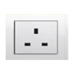
| Fig 4: 3-Pin Socket |
A socket is a type of equipment used in electrical wiring lines that always has an electrical connection. According to the need, it can be supplied to the electrical equipment. In case of electric iron, electric hand drill machine and electric hand grinder etc. two-pin socket with earth terminal is used. Also, three-pin sockets are used for electrical appliances that have a metal body and are likely to be electrified. Eg – Refrigerator, room heater, table heater, hot-plate, electric oven etc.
04. Light Holder
 |
| Fig 5: Light Holder |
A Light holder, commonly referred to as a stockholder, is any person, company, or institution that owns at least one share of a company's stock. Light Holders own the company, they enjoy the benefits of the company's success in the form of increased stock appreciation. Unlike owners of sole proprietorships or partnerships, corporate Light holders are not personally liable for the company's debts and other financial obligations. If the company goes bankrupt, its creditors cannot demand payment from the Light holders.
Thank You for visiting the website. Keep visiting for more Updates
$ads={2}
Frequently Asked Questions
What is the series parallel testing board?
This diagram shows the series of parallel electrical testing boards. In this circuit diagram, we use a two-way switch light and a three-pin socket. First, we need to input the phase line to the two-way switch and then from the switch to the socket or light.
How do you test a domestic electrical circuit?
To test the wiring in your home set your multimeter to the AC of the voltage to the 2 hundred volts setting. Plug the probes into the multimeter and then place the other ends into the holes of one of your sockets. Give it a few seconds, and you should get a reading of what voltage is in the circuit.
How is a series circuit made?
A series circuit diagram is one in which all circuit elements are arranged in a single path. In a series circuit, the current flow through all elements is the same, but the voltage drop across each element is different. A parallel circuit is one in which circuit elements are arranged in different branches of the circuit diagram.
How do I run parallel testing?
Parallel testing could be executed either with test automation tools or by manual means. In parallel testing, the automation framework is integrated with cloud-based solutions or virtualization that helps maintain and monitor device management to scale automated tests across platforms concurrently.
What is the series-parallel method?
The basic idea of the series-parallel method is to successively use equivalent resistance rules for series or parallel resistors in a sequence of steps. First, we replace all the resistors in series with their equivalent of the resistances. This step usually leaves some of the resistors in parallel.


Post a Comment
Do leave your comments