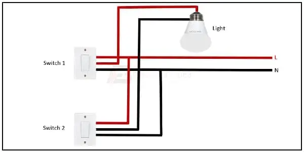
Single Phase Energy Meter Connection Diagram:
This diagram shows how to connect the single-phase energy meter connection. Single-phase energy meter has a total of 2 input ( line and neutral ) terminals and 2 output (line and neutral) terminals. In this circuit diagram, we want to describe how to connect 3 single-phase meters in the grid line. If you want to more clearly details about this diagram please check our youtube video.
Diagram of Signle Phase Energy Meter wiring:
Components Need for this Project:
You can get the components from any of the sites below:
- Single Phase Energy Meter [See Buy Click Amazon]
$ads={1}
Read Also:
Components used to make the Single Phase Energy Meter wiring:
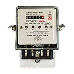
01. Single Phse Energy Meter
 |
| Fig 2: Single Phse Energy Meter |
Thank You for visiting the website. Keep visiting for more Updates.
Frequently Asked Questions
The basic working of the Single-phase induction-type Energy Meter is only focused on two mechanisms: The mechanism of rotation of an aluminum disc which is made to rotate at a speed proportional to the power supply. Mechanism of counting or displaying the amount of energy transferred.
A single-phase meter also referred to as a credit meter, KWh meter, or check meter are electrical meter designed for use in measuring the power supply consumption in a single-phase power supply. These meters, however, only deal with the Alternating current flow (AC power) supply and not the Direct current (DC) power supply.
With a single-phase, two-wire system (Figure 2), the voltage and current flow detected by the wattmeter are equal to the total power dissipated by the load. The voltage is measured between the 2- wires and the current is measured in the wire supplying power to the load, often called the hot wire.
When it comes to distributing the power, a single-phase connection uses neutral and phase wires. The neutral wire acts as a returning path for the current flow and the phase wires carry the load. In a single-phase connection, the voltage starts at 230 V and has a frequency of about 50 Hertz.
Single-phase systems are the simplest electrical circuit diagrams. They require only two lines: one for the power supply to go in and the other is a return path for the current. These are often called Line 1 and Line 2, or Line 1 or Neutral.
You may like these posts

8-pin relay using light sensor wiring to house loads like light.

An Electric Meter, Or Energy Meter, is a Device That Measures

the Subcircuits and Final sub-circuits including their associated

a 2-wire alternating Current Power Circuit. There is 1 Power Wire

The Switch Simply Open (off) or Closes (on) The Connection

They are connected so That Under Normal Conditions,


Post a Comment
Do leave your comments