Single Phase Distribution Board Wiring | distribution board wiring

Single Phase Distribution Board Wiring | distribution board wiring

Single Phase Distribution Board Wiring:

This Diagram Shows A Distribution Board is a Safe System Designed for Houses or Buildings That Included Protective Devices, Isolator Switches, Circuit Breakers, and Fuses to Connect Safely The cables and wires to the Subcircuits and Final sub-circuits including their associated Live (Phase) Neutral and Earth. A Distribution Board is a Component of an Electricity Supply System That Divides an Electrical Power Feed into Subsidiary Circuits While Providing a Protective Fuse or Circuit Breaker for Each Circuit in a Common Enclosure.

Diagram of Single Phase Distribution Board wiring:

Single Phase Distribution Board Wiring
Fig 1: Single Phase Distribution Board Wiring


Components Need for this Project:

You can get the components from any of the sites below:

  1. Single Phase Energy Meter [See Buy Click Amazon]
  2. RCCB [See Buy Click Amazon]
  3. DP MCB [See Buy Click Amazon]
  4. Busbar [See Buy Click Amazon]
*Please note: These are affiliate links. I may make a commission if you buy the components through these links. I would appreciate your support in this way!

$ads={1}

Read Also:

Components used to make the Single Phase Distribution Board Wiring:

01. Single Phase Energy Meter

Single Phase Energy Meter
Fig 2: Single Phase Energy Meter
The measuring device with the help of which the electric power or energy of a circuit is measured is called Energy Meter (Energy Meter). Also called a watt-hour or kilowatt-hour meter. For home appliances, we used a single-phase energy meter. The single-phase energy meter is directly connected between the line and the load. Both coils produce their magnetic fields, when the meter is connected to the supply line, and the load. Energy meters are used in homes and in industrial applications where we want to found that how much energy is being consumed by home appliances and electrical equipment.


02. RCCB

RCCB
Fig 2: RCCB
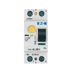
The RCCB (Residual Current Circuit Breaker) or RCCB is an electrical protective device.Residual Current Circuit Breaker is specially designed to protect the electrical circuit against earth fault and human from electrical shock.In this, under normal condition the load is always connected in between the phase terminal to neutral terminal, hence the flow of phase current is equal to neutral current.Earth fault or fault in a power system can cause excess heating, more power consumption, burning or fire, etc. So, protection against earth leakage is very important.

03. DP MCB

DP MCB
Fig 4: DP MCB
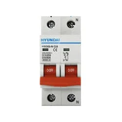
Double pole MCB can control two wires. This circuit breaker is generally used in single-phase electric lines. Double pole MCB circuit breaker input has two wires supply two wires and an output. In a single-phase line, A double-pole MCB circuit breaker is used to give good production. This circuit breaker is provided through phase and neutral circuit breaker, it is very safe. This circuit breaker is preferred for home appliances. A DP MCB usually trips for 2 reasons 1. Overload 2. Short circuit.


04. Busbar

Busbar
Fig 5: Busbar
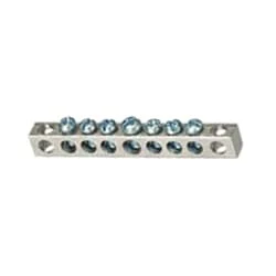
Busbar is a type of power transmission sheet. It is made of copper or brass or aluminum. Busbar is mostly used in factories. We supply the power from the transformer to the busbar. Busbars have electricity. We take the electricity from this busbar to the circuit breaker. The busbar is drilled with a drill machine and the cable is connected with a nut bolt. The advantage of using a busbar is that through it we can provide multiple power connections in multiple places very easily.

Thank You for visiting the website. Keep visiting for more Updates


$ads={2}

Frequently Asked Questions

How a distribution board is wired?

The main supply cable comes into the board and is then distributed to the breakers and from there to all the circuits lights fan plugs etc. This video shows a Single Phase Distribution Board Wiring Diagram. distribution board DB is where the electrical power supply is distributed from within the Circuit diagram building home.

What is the wiring system of single-phase?

Single-phase power supply is a 2-wire alternating current (AC) power supply circuit. Typically, there is one power wire—the phase wire—and one neutral wire, with current flowing between the power wire (through the load) and the neutral wire.

Why does single-phase have 3 wires?

In most of the world, 2 wires suffice for 220 volts single phase (not counting any additional earth protective grounds). In the US, the 240 volts are center center-tapped at the transformer, so you end up with 3 wires- the neutral (center tap) and 2 hot wires of 120 volts each to neutral, and 240 volts hot to hot.

Why does single-phase have 2 wires?

Single phase means you have 2 wires coming from the power supply street, an active wire, usually red, and a neutral Project system wire, always black. To simplify, in a single-phase power supply, the energy flows in via the active, through your meter and main Circuit diagram switch, and onward via RCD/circuit diagram breakers, into the wiring, and to your current appliances.

How to wire the 3-phase to a single phase?

By far the simplest method of obtaining a single-phase output from a 3-phase power supply is to place a single-phase transformer across 2 phases of a 3-phase power supply. The effect of this system is to pull the full rated current in 2 of the supply lines and zero current in the Circuit diagram third line.

Post a Comment

Do leave your comments

Previous Post Next Post

Advertisements

Advertisements

Blogging Experiment
Electronic Experiment Subscribe our Youtube Channel
Subscribe