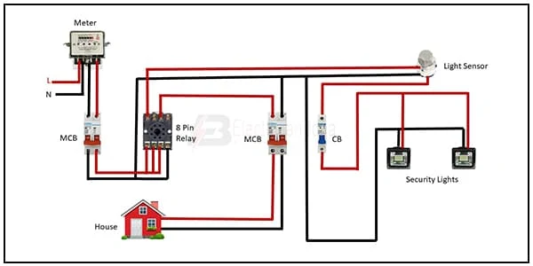
8-Pin Relay Using light sensor wiring:
This diagram shows how to connect the 8-pin relay using light sensor wiring. In this circuit diagram, we just try to describe simply how to connect an 8-pin relay using light sensor wiring to house loads like light. This diagram is for single-phase house wiring. So you can wire your house or office like this diagram very easily. If you want to learn how to connect this circuit clearly you can follow our youtube video link in below.
Light sensor Wiring using 8-pin Relay:
Components Need for this Project:
You can get the components from any of the sites below:
- Single phase Energy Meter [See Buy Click Amazon]
- DP MCB [See Buy Click Amazon]
- SP MCB [See Buy Click Amazon]
- 8-Pin Relay [See Buy Click Amazon]
- Security Light [See Buy Click Amazon]
- Light Sensor [See Buy Click Amazon]
Read Also:
Components used to make the Light sensor wiring:
01. single phase Energy Meter
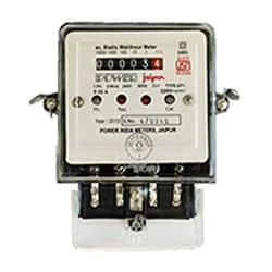 |
| Fig 2: Single phase Energy Meter |
The measuring device with the help of which the electric power or energy of a circuit is measured is called Energy Meter (Energy Meter). Also called a watt-hour or kilowatt-hour meter. For home appliances, we used a single-phase energy meter. The single-phase energy meter is directly connected between the line and the load. Both coils produce their magnetic fields, when the meter is connected to the supply line, and the load. Energy meters are used in homes and in industrial applications where we want to found that how much energy is being consumed by home appliances and electrical equipment.
02. DP MCB
 |
| Fig 3: DP MCB |
Double pole MCB can control two wires. This circuit breaker is generally used in single-phase electric lines. Double pole MCB circuit breaker input has two wires supply two wires and an output. In a single-phase line, A double-pole MCB circuit breaker is used to give good production. This circuit breaker is provided through phase and neutral circuit breaker, it is very safe. This circuit breaker is preferred for home appliances. A DP MCB usually trips for 2 reasons 1. Overload 2. Short circuit.
03. SP MCB
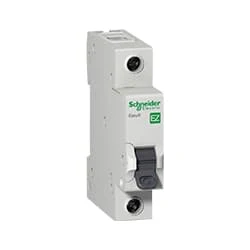 |
| Fig 4: SP MCB |
04.8-pin Relay
 |
| Fig 5: 8-Pin Timer |
05. Security Light
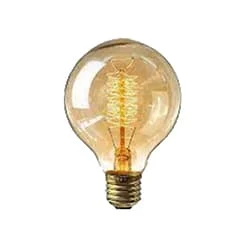 |
| Fig 6: Seceurity light |
06. Light Sensor
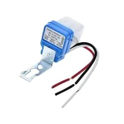 |
| Fig 7: Light Sensor |
Frequently Asked Questions
Relays are electrically operated switches that open and close the circuit diagrams by receiving electrical signals from outside power supply sources. They receive an electrical signal and send the signal to other equipment by turning the Circuit diagram switch on and off.
A 4-pin relay is a simple Circuit diagram structured relay. The pin numbers on a 4-pin power supply relay are 85, 86, 87, and 30. Pin 30 is the power supply for a relay, and pin 86 acts as the Circuit diagram switch for that pin. 85 is the grounding pin and 87 is the pin power supply connected to a device.
Using an 8-channel relay means that the relay module has 8 individual relays, each capable of controlling a separate circuit. This allows for the centralized control of multiple devices or circuits using a single control signal.
The Relay is a digital normally open switch that controls a relay power supply capable of switching much higher voltages and currents than your normal Arduino project system boards. When set to LOW, as the LED will light up and the relay will close allowing Currenttlou current to flow. The peak voltage Circuit diagram capability is 250V at 10 amps.
Relays are electrically operated Project system switches that open and close the circuits by receiving Power supply electrical signals from outside sources. Some people may associate “relay” with a racing competition where members of the team take turns passing batons to complete the race.

Post a Comment
Do leave your comments