Air Compressor Starter Wiring diagram:
This diagram shows how to connect the air compressor starter wiring diagram. In this article, we try to clearly describe how to connect the air compressor starter wiring diagram very easily. In this circuit, we use 2 capacitors, one voltage relay, and an air compressor. If you want to see this project animation diagram please follow our youtube video.
Diagram of Air compressor starter wiring:
Components Need for this Project:
You can get the components from any of the sites below:
$ads={1}
Read Also:
Components used to make the Air compressor starter wiring:
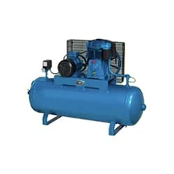
01. Air Compressor
 |
| Fig 2: Air Compressor |
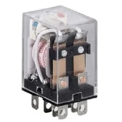
02. Relay
 |
| Fig 3: Relay |
03. Capacitor
 |
| Fig 4: Capacitor |
Thank You for visiting the website. Keep visiting for more Updates.
Frequently Asked Questions
When the specified system pressure is reached, a diaphragm inside the pressure switch pushes against a mechanism that forces the electrical contacts apart, breaking the circuit and stopping the motor. At the same time, the pressure relief valve opens and relieves back pressure caught between the pump and the check valve.
The compressor is the heart of the refrigeration of the system. The compressor acts as the pump that moves the refrigerant through of the system. Temperature sensors start the compressor's action.
The W wire is connected to your heat system. If your thermostat the heated, you will have a white wire. The Y wire is yellow or connects to your air conditioning compressor. The G wire is green or connects to the fan.
Check for the simplest remedies first, such as whether the power cable is still connected and the switches are all in the right position. You may also need to check or replace fuses, reset breakers, check the pressure switch, and activate a reset of the switch to get the machine back into power supply mode.
The power and speed of the compressor are controlled by the driver. The speed could be varied with some compressors. Compression is most effective within this range. It is possible to vary the pressure or gas output in such a case by altering the speed of the driver.
You may like these posts

an 8-pin relay, and a light. We need to connect all components

, an RCCB ( Residual Current Circuit Breaker ), a relay switch,

In this circuit, we use a switch and four lights.

ture Circuit Breakers), an ELCB ( Earth Leakage Circuit Breaker ),

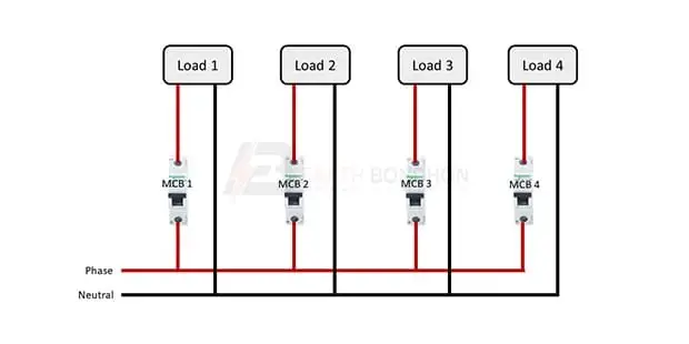
Single phase MCB wiring. In this circuit, we use four SP MCB

an RCCB ( Residual Current Circuit Breaker ), and two SP MCBs


Post a Comment
Do leave your comments