Relay to control lamps wiring:
This diagram shows how to make a Relay To Control Lamps Wiring. Control Relay Circuit. In this circuit, we use a DP MCB ( Double Pole Miniature Circuit Breaker), an RCCB ( Residual Current Circuit Breaker ), a relay switch, four NO switches ( Normal Open ), and three lights. We need to connect all components like our diagram. Now this circuit is ready for use. If you want to know more about this circuit please check our youtube video below the post.
Diagram of relay to control lamps wiring:
Components Need for this Project:
You can get the components from any of the sites below:
- DP MCB [See Buy Click Amazon]
- RCCB [See Buy Click Amazon]
- Relay [See Buy Click Amazon]
- Light [See Buy Click Amazon]
- NO Switch [See Buy Click Amazon]
Read Also:
Components used to make the control relay circuit:
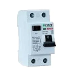
01. DP MCB
 |
| Fig 2: DP MCB |
Double pole MCB can control two wires. This circuit breaker is generally used in single-phase electric lines. Double pole MCB circuit breaker input has two wires supply two wires and an output. In a single-phase line, A double-pole MCB circuit breaker is used to give good production. This circuit breaker is provided through phase and neutral circuit breaker, it is very safe. This circuit breaker is preferred for home appliances. A DP MCB usually trips for 2 reasons 1. Overload 2. Short circuit.
02. RCCB
 |
| Fig 3: RCCB |
The RCCB (Residual Current Circuit Breaker) or RCCB is an electrical protective device.Residual Current Circuit Breaker is specially designed to protect the electrical circuit against earth fault and human from electrical shock.In this, under normal condition the load is always connected in between the phase terminal to neutral terminal, hence the flow of phase current is equal to neutral current.Earth fault or fault in a power system can cause excess heating, more power consumption, burning or fire, etc. So, protection against earth leakage is very important.
03. Relay
 |
| Fig 4: Relay |
This relay is known as 8 pin relay because it has 8 terminals. When coil power is supplied. A magnetic induction is created due to which the connected sheet of the Com part moves towards the NO part changing to NO-NC. The former NC region loses conductivity and becomes NO. Thus, as long as power is supplied to the coil, the NO and NC positions will remain in the alternating state, and when the power is removed from the coil, it will return to its original position. This is basically how a relay switch works.
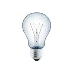
04. Light
 |
| Fig 5: Light |
CFLs work in a completely different way from ordinary lamps, they work by using a different process called fluorescence rather than generating light from heat. A typical light bulb wastes 90% of energy and converts only 10% of energy into light, this is where CFL has the biggest advantage. CFL- Curved or conical glass tube filled with argon and a small amount of mercury vapor. The inner wall of the glass is coated with fluorescent material. CFL- It is manufactured using the principle of creating fluorescent light. CFL- Originally white in color but now the construction and use of CFLs producing colored light has become popular.
05. NO Switch
 |
| Fig 6: NO Switch |
The operator switch has its contact in Normally Open condition. To make Ladder Logic you need to understand NO contact. A Classic Switch has one Input And one Output. In "No Switch," YoungBoy Raps About Ammunition, Murder, Firearms, and Firearm Attachments Such as a Switch. The contact of the switch whose contact is already open is NO. That is enough to understand. no switch in a circuit, then the circuit will not function as intended. to write a program such that when the red light is on, This switch is now in normally open condition. When you push the switch it will close and the red light will turn on.
Thank You for visiting the website. Keep visiting for more Updates.
Frequently Asked Questions
The control circuit functions as the coupling between the input and output circuits. In electromechanical relays, the coil accomplishes this function. A relay output circuit is the portion of the relay that switches on the load and performs the same function as the mechanical contacts of electromechanical relays.
The Relay Station Lighting - DIN is designed to control lights and provides eight isolated latching relay channels. The RS8-L-DIN accepts voltage from 0 to 277 volts and up to 10amps at each load. The relays are single-pole, single-throw, offering a set of eight latching contacts.
Relays are electrically operated switches that open and close the circuits by receiving electrical signals from outside sources. Some people may associate “relay” with a racing competition where members of the team take turns passing batons to complete the race.
Connects to a device that the relay will power when the coil receives sufficient voltage to energize. The device remains off when the relay has no power and switches on when the relay receives power. The terminal connects to the device to power when the relay receives no power.
The "Control circuit voltage” indicates the voltage that will be applied on the input of the slim relay (in order to indicate to the customer the right voltage rating of the relay, if he replaces it). The sockets adapt the operating voltage to the slim-relay which is limited to 60Vdc.


Post a Comment
Do leave your comments