Light Series Circuit wiring:
This diagram shows how to make Series Circuit Wiring Diagram. Series connection diagram. In this circuit, we use a switch and four lights. We need to connect all components like our diagram. Now this circuit is ready for use. This circuit is very simple and easy to make. If you want to know more about this circuit please check our youtube video below the post.
Diagram of light series wiring:
Components Need for this Project:
You can get the components from any of the sites below:
Read Also:
Components used to make the series connection diagram:
01. Switch
 |
| Fig 2: Switch |
A Single-Pole, Single-Throw (SPST) Switch. It's Got one Output and One Input. The Switch will Either be Closed or Completely Disconnected. SPSTs are Perfect for on-off Switching. They're also a Very Common Form of Momentary Switches. SPST Switches are Commonly Used in a Variety of Electrical Circuits and Applications, Such as Turning on And off Lights, Fans, and Other Appliances. They can Also be Used to Control the Flow of Electricity to Different Parts of a Circuit or to Switch Between Different Circuits Altogether.
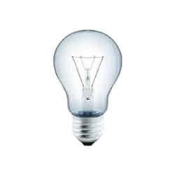
02. Light
 |
| Fig 3: Light |
CFLs work in a completely different way from ordinary lamps, they work by using a different process called fluorescence rather than generating light from heat. A typical light bulb wastes 90% of energy and converts only 10% of energy into light, this is where CFL has the biggest advantage. CFL- Curved or conical glass tube filled with argon and a small amount of mercury vapor. The inner wall of the glass is coated with fluorescent material. CFL- It is manufactured using the principle of creating fluorescent light. CFL- Originally white in color but now the construction and use of CFLs producing colored light has become popular.
Thank You for visiting the website. Keep visiting for more Updates.
Frequently Asked Questions
In a series circuit, all components are connected end-to-end to form a single path for current flow. The total resistance in a series circuit diagram is equal to the sum of the individual resistors, and the total voltage drop is equal to the sum of the Circuit diagram's individual voltage drops across those resistors.
The answer should be the source voltage Power supply divided by the voltage drop of 1 LED. So if your source is 12v, and your LEDs have a voltage drop of 3.5, 12/3.5v, gives you 3 LEDs. If the the forward voltage drop of the LEDs was exactly 3 volts, you'd be able to drive 4 of them, and would not need a Project system current limiting resistor.
Two bulbs in a simple parallel circuit diagram each enjoy the full voltage of the battery power supply. This is why the bulbs in the parallel circuit diagram will be brighter than those in the series circuit diagram. Another advantage to the project system parallel circuit is that if one loop is disconnected, then the other remains powered supply.
Resistors connected head-to-tail are in series. The equivalent overall project system resistance is the sum of the individual and resistance values. Written by Willy McAllister. Components are in series if they are joined end to end like this: We'll work with resistors to reveal the properties of the series connection.
Cells connected in series give a greater resultant voltage Circuit diagram than individual cells. Voltage increases if the power supply number of cells increases. Series circuits do not overheat easily.


Post a Comment
Do leave your comments