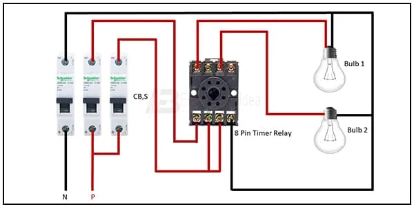
8 Pin Timer Relay Wiring Diagram:
This diagram shows how to connect the 8 Pin Timer Relay Wiring Diagram. In this diagram, we just connect 3 SP MCB( single pole miniature circuit breaker ) 8-pin relays,s, and 2 lights. First, we need to input power to circuit breakers, then connect to the relay and bulb the same way as in the below diagram. If you want more clear details please check our youtube video.
Doagram of 8 Pin Timer Relay Wiring:
Components Need for this Project:
You can get the components from any of the sites below:
$ads={1}
Read Also:
Components used to make the 8 Pin Timer Relay Wiring:
01. 8-Pin Timer
 |
| Fig 2: 8-Pin Timer |
02. SP MCB
 |
| Fig 3: SP MCB |
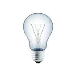
03. Light
 |
| Fig 4: Light |
Thank You for visiting the website. Keep visiting for more Updates.
Frequently Asked Questions
In this video, we explain how an 8-pin electromagnetic relay works, an 8-pin relay has 2 NO contacts and 2 NC contacts. For common relays, namely pin 1 or pin 8, NO contact pin 1 to pin 3 and pin 8 to pin 6 NC contact pin 1 to pin 4, or pin 8 to pin 5.
The 8-channel relay Module is also able to control various appliances and other types of equipment with a large current. Red working status indicators of the lights are conducive to safe use. Widely used for all MCU control, industrial sector, PLC control, or smart home control.
This is a standard 8-pin IC base that allows the user to connect the ICs with the circuits. IC sockets are generally for preventing damage to ICs from soldering while testing multiple circuit diagrams. These are made from Black Thermoplastic or tin-plated alloy contacts.
Description.This 8-channel relay interface board could control various appliances and other equipment with high current flow. It could be controlled directly by any microcontroller. This product is a replacement for VMA436.
The Relay is a digital normally open switch that controls a relay capable of switching much higher voltages and current flow than your normal Arduino boards. When set to LOW, the LED will light up or the relay will close allowing current to flow. The peak of the voltage capability is 250V at 10 amps.
You may like these posts

ln this circuit, we use a switch and two lights.

In this circuit, we use a fuse, an indicator, a switch,

This circuit is very simple and easy to make. If you want

Socket Outlet Wiring. In this circuit, we use four 3-Pin sockets.

Then connect the light with the switch. Now this circuit

In this circuit, we use a single-phase energy meter, a DP MCB


Post a Comment
Do leave your comments