Electrical Outlet Box Installation:
This Diagram shows how to make Electrical Outlet Box Installation. Socket Outlet Wiring. In this circuit, we use a fuse, an indicator, a switch, two power sockets, and two switches. First, we need to connect all components with a phase connection. Then connect all components with a neutral connection. Now this circuit is ready for use. This circuit is very simple and easy to make. If you want to know more about this circuit please stay with our website and check our youtube video below the post.
Diagram of Socket Outlet wiring:
Components Need for this Project:
You can get the components from any of the sites below:
- Fuse [See Buy Click Amazon]
- Indicator [See Buy Click Amazon]
- Switch [See Buy Click Amazon]
- 3 Pin Socket [See Buy Click Amazon]
Read Also:
Components used to make the 220v AC line socket wiring:
01. Fuse
 |
| Fig 2: Fuse |
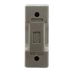
A fuse is an electrical, electronic, or mechanical device that protects a circuit from excessive current or overload. The metal of the fuse is made or designed in such a way that it can carry a very small amount of current. When short-circuited or overloaded, the high-flow current generates thermal heat that melts the fuse's metal or element and creates a gap. This gap interrupts the flow of current in the fuse. Basically, this is how a fuse works. If the fuse is once blown or damaged it needs to be replaced to allow current to flow again in the circuit.
02. Indicator
 |
| Fig 3: Indicator |
An electric current Flow Indicator Senses The electrical Current Through an electrical device And produces visible feedback to Indicate Proper Operation. The Current Flow Indicator Has Voltage And Current Regulation Craving First And Second Inputs Connected To The First And Second Conductors, Respectively. This Publication Provides updated Statistics on a Comprehensive Set of social, Economic, Financial, and Environmental Measures as Well as Select Indicators for Sustainable Development Goals.
03. Switch
 |
| Fig 4: Switch |
A Single-Pole, Single-Throw (SPST) Switch. It's Got one Output and One Input. The Switch will Either be Closed or Completely Disconnected. SPSTs are Perfect for on-off Switching. They're also a Very Common Form of Momentary Switches. SPST Switches are Commonly Used in a Variety of Electrical Circuits and Applications, Such as Turning on And off Lights, Fans, and Other Appliances. They can Also be Used to Control the Flow of Electricity to Different Parts of a Circuit or to Switch Between Different Circuits Altogether.
04. 3 Pin Socket
 |
| Fig 5: 3-Pin Socket |
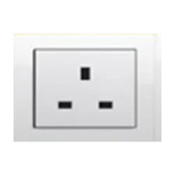
A socket is a type of equipment used in electrical wiring lines that always has an electrical connection. According to the need, it can be supplied to the electrical equipment. In case of electric iron, electric hand drill machine and electric hand grinder etc. two-pin socket with earth terminal is used. Also, three-pin sockets are used for electrical appliances that have a metal body and are likely to be electrified. Eg – Refrigerator, room heater, table heater, hot-plate, electric oven etc.
Thank You for visiting the website. Keep visiting for more Updates.
Frequently Asked Questions
Typically, the black or red wire goes to the Circuit diagram brass-colored screw (hot), the Circuit diagram white wire to the silver-colored screw (neutral), and the green or bare wire to the power supply green screw (ground). Wrap the hook around the screw in a clockwise direction. Push the outlet back into the Project System electrical box and secure it with the screws.
For safety reasons, as it is better to work with a licensed Circuit diagram electrician to install an outlet in your home. They'll also be able to ensure you get the power supply coverage you need. If you have experience and are comfortable running and electrical wiring, then you can do it yourself with the instructions on the power supply shared below.
There are different types of electrical wiring systems such as tee systems, Loop-in systems, cleat wiring, batten wiring, casing and capable wiring, lead Sheathed wiring, and conduit wiring. Electric circuit diagram wiring in residences and buildings is known as a domestic circuit diagram.
If your house was built prior to 1950, you'll need to consider the type of wiring the home has, for instance, copper, aluminum, or knob and tube (k&t). If it is an older house, and it has never been completely rewired, it could have a knob and tube wiring Circuit diagram.
Here are some key reasons why proper electrical wiring is essential: Prevent Electrical Hazards: Correct wiring methods and materials ensure the safe transmission of electricity, reducing the risk of electrical hazards such as short circuits, electric shocks, and fires.


Post a Comment
Do leave your comments