1 Switch 2 Bulb wiring diagrm:
This Diagram shows how to make a 1 Switch 2 Bulb wiring diagram. How to connect light switch. In this circuit, we use a switch and two lights. First, we need to connect the switch, then connect the lights with the switch. Now this circuit is ready for use. This circuit is very simple and easy to make. If you want to know more about this circuit please stay with our website and check our youtube video below the post.
Diagram of light wiring:
Components Need for this Project:
You can get the components from any of the sites below:
Read Also:
Components used to make the 2 light for 1 switch:
01. 2-way Switch
 |
| Fig 2: 2-way Switch |
The two-way switch is a type of multiway switch. Multiway switches have more points and can be controlled in multiple ways simultaneously. The middle connection normally goes to the load and the two side connections act as switches. Again, the opposite is also true if it is used in the lamp connection.It is a type of switch that has three wire connections. And it really has no off or on. Both sides can be turned on or off depending on how you connect one to the other. The two-way switch is a type of multiway switch. Multiway switches have more points and can be controlled in multiple ways simultaneously. Two Way Switch has three wire connection system.
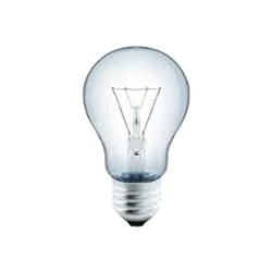
02. Bulb
 |
| Fig 3: Bulb |
CFLs work in a completely different way from ordinary lamps, they work by using a different process called fluorescence rather than generating light from heat. A typical light bulb wastes 90% of energy and converts only 10% of energy into light, this is where CFL has the biggest advantage. CFL- Curved or conical glass tube filled with argon and a small amount of mercury vapor. The inner wall of the glass is coated with fluorescent material. CFL- It is manufactured using the principle of creating fluorescent light. CFL- Originally white in color but now the construction and use of CFLs producing colored light has become popular.
Thank You for visiting the website. Keep visiting for more Updates.
Frequently Asked Questions
Wire them in parallel and either can turn the light on, both must be off for the bulb to be off (that's called an OR function). Wire them with the Circuit diagram normally closed contacts connected and between the 2 switches. Similarly, wire the normally open contacts together.
Yes, you can use a 2-way switch for a 1-way switching Circuit diagram. In fact, many manufacturers of Circuit Diagram don't offer a 1-way switch anymore, they only offer 2-way switches. This is because the cost of manufacture is very similar, therefore there is little to gain from manufacturing one-way-only switches.
You would use a 2-way light switch Circuit diagram when you have 2 switches controlling 1 light, for instance in a hallway, where you have a switch at both ends of the hallway that controls the hallway light. You are able to switch the light on and off from either end of the Power supply hallway.
Connect the Line (brown) wire coming from the light together with the black wire from the 3 Core & Earth cable into the L1 terminal of the two-way switch. Connect the blue wire with the brown sleeve coming from the Circuit diagram light to the L2 terminal, together with the 3 Core & Earth cable's grey wire.
This is the most common Project system residential service in North America. Line 1 to neutral and Line 2 to neutral are used to power supply 120-volt lighting and plug loads. Line 1 to Line 2 is used to power 240-volt single-phase loads such as a water heater, electric range, or air conditioner.


Post a Comment
Do leave your comments