DoorBell wiring multiple Switch and Lamp
This diagram shows DoorBell wiring multiple Switch and Series lamp connections. In this diagram, we use five 2 way switches, five lights, and a doorbell. Here we connect all lights in the series and connect the switch in the series. If we press any switch the doorbell will ring and the connected light also will be on. We can control this bell on any of these 5 switches.
Diagram of DoorBell with multiple Switch and Lamp wiring
Components Need for this Project:
You can get the components from any of the sites below:
$ads={1}
Read Also:
Components used to make the DoorBell wiring:
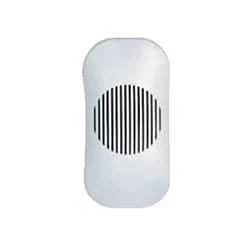
01. Door Bell
 |
| Fig 2: Door Bell |
02. Switch
 |
| Fig 3: Switch |
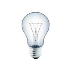
03. Light
 |
| Fig 4: Light |
Thank You for visiting the website. Keep visiting for more Updates.
Frequently Asked Questions
The doorbell switch has 2- terminals that are wired to the doorbell transformer located in the house. The transformer is a metal box with 2- terminals connected to the doorbell wires. It takes the standard electrical to the voltage in your home, in most cases 110 to 120 volts, or lowers it to about 10 to 24 volts.
On one side, the transformer will have 3- wires that connect to your home's power supply. Usually, they are connected by wire nuts. On the other side, the transformer will have 2- screw terminals connected to two doorbell wires. Disconnect the 3- wires that connect the transformer to your home's power supply.
A doorbell transformer wires into your electrical system or allows you to connect your doorbell push button or chime at a much lower voltage. They could be located inside or outside of your home but are usually attached to an electrical junction box in an inconspicuous location.
Not usually. In some odd place in the home, a transformer will be attached/wired to an electrical junction box like this. The transformer would reduce the voltage from 120V (in the US) to between 10 to 24 V. The 2- wires coming off the transformer will power supply the doorbell system.
Wireless doorbells of the systems have no physical wiring connecting the doorbell button outside to the doorbell receiver and chime inside the house. Rather than an electrical wiring a wireless doorbell uses radio waves to transmit the signal.
You may like these posts

then connect to light then neutral wire input to light.

In this circuit, we just use 5 lights and 6 switches.

Here first we input power from the meter to DP MCB, then

a light, a switch, and a DP MCB ( Double Pole Miniature Circuit)

First input phase line to the switch then from the switch

This diagram shows how to make a series and parallel circuit


Post a Comment
Do leave your comments