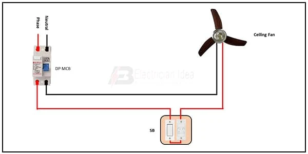
Ceiling Fan Regulator Connection diagram:
This diagram shows the Ceiling Fan Regulator Connection diagram. Wires from another terminal of each switch are then connected to electrical devices. In case the fan, its speed is needed to be controlled, the speed regulator is connected first, then the wire from another terminal of the speed regulator is taken to the fan. In this diagram, we just describe how to connect a ceiling fan with a switch and a regulator with DP MCB.
Diagram of Ceiling Fan Regulator Connection wiring:
Components Need for this Project:
You can get the components from any of the sites below:
- DP MCB [See Buy Click Amazon]
- Ceiling Fan [See Buy Click Amazon]
- Switch [See Buy Click Amazon]
- Fan Regulator [See Buy Click Amazon]
$ads={1}
Read Also:
Components used to make the Fan Regulator Connection:
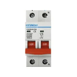
01. DP MCB
 |
| Fig 2: DP MCB |
02. Ceiling Fan
 |
| Fig 3: Ceiling Fan |
03. Switch
 |
| Fig 3: Switch |
04. Fan Regulator
 |
| Fig 4: Fan Regulator |
Thank You for visiting the website. Keep visiting for more Updates.
Frequently Asked Questions
Connect the red/live wire of the fan to the first terminal of the capacitor. Then connect the blue wire of the fan to the second terminal of the capacitor. Put a wire nut over both wires. Insert the wires in the wire connector.
Using a fan without a regulator could potentially lead to damage if the fan is designed to be used with a regulator. Without a regulator, the fan may operate at a constant speed, which could cause the motor to overheat or potentially lead to damage over time.
It sounds like there may be a few potential reasons why your fan electronics regulator is not working properly. It could be due to a faulty wiring connection, a defective regulator unit, or an issue with the fan motor itself.
The basic mechanism of an electric regulator includes the presence of resistors to reduce the voltage of the ceiling fan. The downside of this type of regulator is that it heats up while controlling the voltage or hence, no electricity is saved by decreasing its speed.
Due to the 2- different phases in each winding, magnetic rotation is created and thus the rotor starts rotating. Therefore, a capacitor is used in a fan to create a phase difference in the current flow of the two windings which in turn creates a magnetic flux and makes the rotor of the fan rotate.
You may like these posts

Much More Flexible in Terms of Usage Than 2 Smaller 16A Radials.

a Good, Directed Beam of Light for Activities like Reading.

At The Same Time, Efficiency Also Saves Money And Creates Jobs.

An SPD (A Circuit Protection Device) is a Current or Voltage

A 2-Way Light Switch is a Switch That can be Used in Conjunction

A “toggle” is a Small wooden rod that is used as a clothing


Post a Comment
Do leave your comments