toggle switch on indicator off | the toggle switch on/off symbols
Toggle switch on indicator off Connection:
This diagram shows Toggle Switches Have an Operating Lever That Can be Pushed Up And Down or Left and Right to Switch an Electrical Circuit. A “toggle” is a Small wooden rod that is used as a clothing fastener in the place of buttons. On-off-on Toggle Switches are Variations of The on-on Design. They add a Third, Neutral-off Position in the Center. The off Position is the Default Resting Position and both on Positions will Click Back to this Once Released.
Diagram of toggle switch on indicator off wiring:
 |
| Fig 1: toggle switch on indicator off |
Components Need for this Project:
You can get the components from any of the sites below:
- Switch [See Buy Click Amazon]
- Indicator [See Buy Click Amazon]
- Bulb [See Buy Click Amazon]
*Please note: These are affiliate links. I may make a commission if you buy the components through these links. I would appreciate your support in this way!
$ads={1}Read Also:
Components used to make the toggle switch on indicator off:
01. Switch
 |
| Fig 2: Switch |
A Single-Pole, Single-Throw (SPST) Switch. It's Got one Output and One Input. The Switch will Either be Closed or Completely Disconnected. SPSTs are Perfect for on-off Switching. They're also a Very Common Form of Momentary Switches. SPST Switches are Commonly Used in a Variety of Electrical Circuits and Applications, Such as Turning on And off Lights, Fans, and Other Appliances. They can Also be Used to Control the Flow of Electricity to Different Parts of a Circuit or to Switch Between Different Circuits Altogether.
02. Indicator
 |
| Fig 3: Indicator |
An electric current Flow Indicator Senses The electrical Current Through an electrical device And produces visible feedback to Indicate Proper Operation. The Current Flow Indicator Has Voltage And Current Regulation Craving First And Second Inputs Connected To The First And Second Conductors, Respectively. This Publication Provides updated Statistics on a Comprehensive Set of social, Economic, Financial, and Environmental Measures as Well as Select Indicators for Sustainable Development Goals.
03. Bulb
 |
| Fig 4: Bulb |
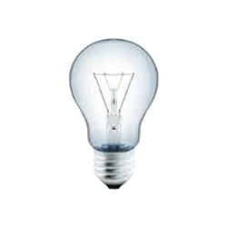
CFLs work in a completely different way from ordinary lamps, they work by using a different process called fluorescence rather than generating light from heat. A typical light bulb wastes 90% of energy and converts only 10% of energy into light, this is where CFL has the biggest advantage. CFL- Curved or conical glass tube filled with argon and a small amount of mercury vapor. The inner wall of the glass is coated with fluorescent material. CFL- It is manufactured using the principle of creating fluorescent light. CFL- Originally white in color but now the construction and use of CFLs producing colored light has become popular.
Thank You for visiting the website. Keep visiting for more Updates
$ads={2}
Frequently Asked Questions
What is the symbol of switch off?
A common style of a switch is a rocker Circuit diagram design, which includes on/off markings. To meet the power supply standard IEC 60417, the symbol for ON is “I” (a straight line) and the Project system symbol for OFF is “O” (a circle).
Does toggle mean turn off?
Definition: A toggle Currenttlou switch is a digital on/off switch. Toggle switches are best used for changing the Circuit diagram state of Project system functionalities and preferences. Toggles may replace 2 radio buttons or a single Project system checkbox to allow users to choose between 2 opposing states.
What is the difference between a switch on and a switch off?
When the switch is turned off and on, it breaks the circuit diagram, and no current flows. When you turn on the power supply switch, the circuit diagram is complete and the current Project system starts to flow.
How does a switch work answer?
When we turn on a switch, current flows to the circuit and the devices connected get an electric current supply. When the switch is turned off, it breaks the circuit and current is no longer available to the circuit or device attached.
Which is a type of solid-state switch?
Solid state relay switches can be classified into 3 different types or "forms", based on the Power supply pole and throw information above. Form A switches are SPST (single pole, single throw) and normally Circuit diagram open (NO). Form B switches are SPST and normally Circuit diagram closed (NC).


Post a Comment
Do leave your comments