4 switch holder connection:
This diagram shows how to connect the 4 switch holder connection. In this circuit diagram, we just try how to connect 4 switches with four light holders easily and also how to connect a DP MCB and socket connection. First of all, we need to input the power supply to DP MCB and then from DP MCB to switches and light holders. If you want to more clearly learn please watch our youtube video.
Diagram of 4 switch holder connection wiring:
Components Need for this Project:
You can get the components from any of the sites below:
- DP MCB [See Buy Click Amazon]
- 4-Gang Switch [See Buy Click Amazon]
- 3-Pin Sokcet [See Buy Click Amazon]
- Light Holder [See Buy Click Amazon]
$ads={1}
Read Also:
Components used to make the Switch Holder connection:
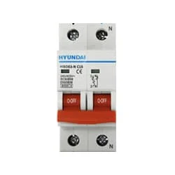
01. DP MCB
 |
| Fig 2: DP MCB |
02. 4-Gang Switch
 |
| Fig 3 : 4-Gang Switch |
03. 3-Pin Socket
 |
| Fig 4: 3-Pin Socket |
04. Light Holder
 |
| Fig 5: Light Holder |
Thank You for visiting the website. Keep visiting for more Updates.
Frequently Asked Questions
Four-way switches have four terminals on them: two for traveler wires coming in, and two for traveler wires going out. The device would usually indicate which two terminals are for “incoming” or “outgoing” wires.
A four-way switch gives you a way to control a light or group of lights from three or more locations when combined with two, three-way switches. A four-pole switch will simply control four, separate circuits with a single switch. A pole is the circuit. A 4-pole switch will control up to 4 circuit diagrams at one time.
If we need to control the light from more than two locations then we simply install a 4-way, or double-pole, double-throw, switch in between the 3-way switches. As a rule, we must always install three-way switches in pairs, and then as many four-way switches as necessary.
There is no limit to the number of four-way switches that can be connected in the circuit as long as the wiring is adequate to carry the load. Typical applications include multi-floor stairways that are centrally illuminated and where it's necessary to control the lighting on any floor level.
In electrical terms, "4 pole" refers to a type of switch, relay, or motor that has four separate circuit diagrams or sets of contacts. This can be used to control multiple circuit diagrams or phases in electrical systems, such as in three-phase motors or multi-phase power supply distribution systems.
You may like these posts

The Different types of Single-Phase Induction Motors vary

a power supply from its primary source to a backup source when

220v ac line overvoltages protection saft line.

If you want more clear details about this diagram please check

220v ac components used are a resistor, capacitor, DIAC,

When the current flows through the bypass circuit diagram.


Post a Comment
Do leave your comments