Fan regulator conection:
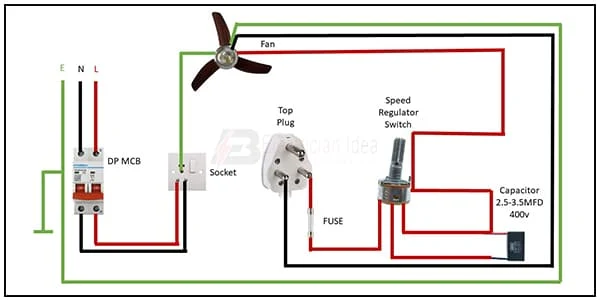
The ceiling fan regulator has spools of wire with different amounts of resistance. TRIAC is used in domestic ceiling fan speed control circuits. In the TRIAC-based Electrical fan regulator circuit. the main line 220v ac components used are a resistor, capacitor, DIAC, and TRIAC.
Fan regulator direct connetion wiring:
Components Need for this Project:
You can get the components from any of the sites below:
- DP MCB [See Buy Click Amazon]
- Top Plug [See Buy Click Amazon]
- Socket [See Buy Click Amazon]
- Fuse [See Buy Click Amazon]
- Speed Regulator [See Buy Click Amazon]
- Capacitor [See Buy Click Amazon]
Read Also:
Components used to make the fan regulator connection:
01. DP MCB
 |
| Fig 2: DP MCB |
Double pole MCB can control two wires. This circuit breaker is generally used in single-phase electric lines. Double pole MCB circuit breaker input has two wires supply two wires and an output. In a single-phase line, A double-pole MCB circuit breaker is used to give good production. This circuit breaker is provided through phase and neutral circuit breaker, it is very safe. This circuit breaker is preferred for home appliances. A DP MCB usually trips for 2 reasons 1. Overload 2. Short circuit.
02. Top Plug
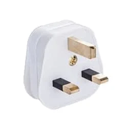 |
| Fig 3: 3-pin top Plug |
Many of us mistake a device that receives power through a 3-pin plug as a 3-phase load. Actually, they are single-phase loads and a 3-pin plug is used in these devices to avoid electrical accidents. This type of plug has three pins called 'Live', 'Neutral', and 'Earthing' which are marked by letters 'L', 'N', and 'E' respectively. The three wires to which these three pins are connected are also colored differently. The earth pin is connected to yellow or green, live pin to red or brown and neutral pin to black or blue wire. Among these pins, the earth pin is the longest and thickest.
03. Socket
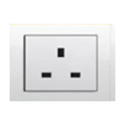 |
| Fig 4: 3-Pin Socket |
A socket is a type of equipment used in electrical wiring lines that always has an electrical connection. According to the need, it can be supplied to the electrical equipment. In case of electric iron, electric hand drill machine and electric hand grinder etc. two-pin socket with earth terminal is used. Also, three-pin sockets are used for electrical appliances that have a metal body and are likely to be electrified. Eg – Refrigerator, room heater, table heater, hot-plate, electric oven etc.
04. Fuse
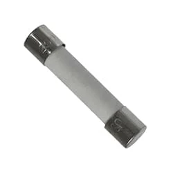 |
| Fig 5: Fuse |
A fuse is an electrical, electronic, or mechanical device that protects a circuit from excessive current or overload. The metal of the fuse is made or designed in such a way that it can carry a very small amount of current. When short-circuited or overloaded, the high-flow current generates thermal heat that melts the fuse's metal or element and creates a gap. This gap interrupts the flow of current in the fuse. Basically, this is how a fuse works. If the fuse is once blown or damaged it needs to be replaced to allow current to flow again in the circuit.
05. Speed Regulator
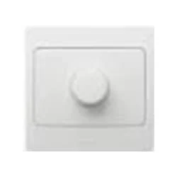 |
| Fig 6: Fan Regulator |
Reduces fan speed by switching on and off. Reducing the speed of the fan, the power Consumption is also Reduced. It is basically a wire wood resistor-based regulator. The large regulators that were used in the past took up more than half of the switchboard space and were very hot. It looks very small in size. Almost equal to a switch. Electrical regulators are basically made by winding copper wire on an iron core. As Electricity Travels Long Distances Through These Wires, Some of The Electrical Energy is Converted Into Heat Energy.
06. Capacitor
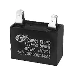 |
| Fig 7: Capacitor |
An MFD or Micro-Farad is a Technical Terminology Used to Describe the Level of Capacity in a Capacitor. Therefore, The Higher The MFD Ratings of a Capacitor, The More Electrical Current Your Capacitor Can Store. A Standard Capacitor may Have an MFD Ranging from 5 to 80 MFD. 50 MFD Volts Which Means it will Work at 370 or 440 VAC. A Dual-Run Capacitor, Such as This 50uf, Combines two Capacitors Into One Unit. 50 MFD 250 Volt Round Capacitor With Mounting Stud and Capacitor has two Screw-type Terminals.
Thank You for visiting the website. Keep visiting for more Updates.
Frequently Asked Questions
Using a fan without a regulator can potentially lead to damage if the fan is designed to be used with a regulator. Without a regulator, the fan may operate at a constant speed, which could cause the motor to overheat and potentially lead to damage over time.
Regulators in ceiling fans are used to control and regulate the speed of the power supply fan. Specifically, regulators control fans by controlling the voltage passing through to the fans. These simple but effective devices have been Circuit diagrams around since the 1950s and come in many types.
Yes, a control power supply regulator can control more than 1 fan, depending on the type of control regulator and the Circuit diagram number of fans you want to control. For example, a simple on/off switch or a basic speed controller can usually only control one fan.
In the fan regulator, the triac used actually chops the AC input voltage. That is it regulates the terminal voltage across the fan input wires. It works on the principle of RC circuit by adjusting the time constant it controls the firing angle of the triac.
A fan regulator increases the power supply speed of a fan by controlling the amount of electrical power supply supplied to the fan motor. This is typically achieved using a variable resistor or electronic circuitry diagram to adjust the voltage or current flowing to the project system motor.

Nice Article :)
ReplyDeleteThanks Brother....
DeletePost a Comment
Do leave your comments