Automatic Transfrer Switch using 8 pin Relay
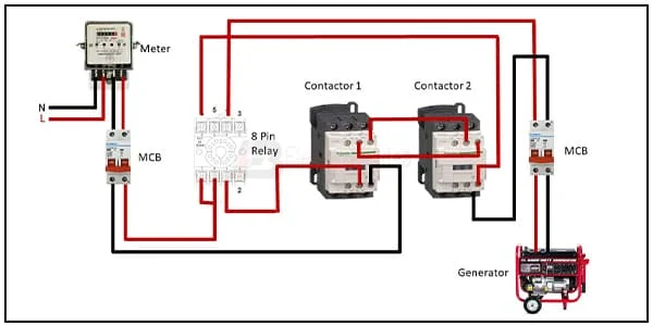
This diagram shows an 8-pin relay connection ats. The terminal connects to the device to power when the relay receives no power. Mini contactor relays are used in the ATS implementation examples of power supply configurations with a priority source or with the option to select the priority source. In this diagram, we want to show a perfect connection ats (Automatic Transfer Switch) using a relay in the grid and generator line. You can follow this circuit diagram to gain knowledge of how to connect ats (automatic transfer switch) using 8 pin relay.
Images of Automatic Transfrer Switch using 8 pin Relay wiring
Components Need for this Project:
You can get the components from any of the sites below:
- Single Phase Energy Meter [See Buy Click Amazon]
- Magnetic Contactor [See Buy Click Amazon]
- DP MCB [See Buy Click Amazon]
- 8 Pin Relay [See Buy Click Amazon]
- Power Generator [See Buy Click Amazon]
$ads={1}
Read Also:
Components used to make the Automatic Transfrer Switch using 8 pin Relay:
01. Single Phase Energy Meter
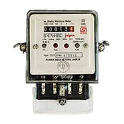 |
| Fig 2: Single Phase Energy Meter |
02. Magnetic Contactor
 |
| Fig 3: Magnetic Contactor |
03. DP MCB
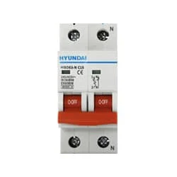 |
| Fig 4: DP MCB |
04. 8 Pin Relay
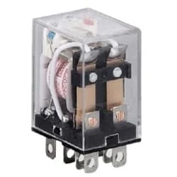 |
| Fig 5: 8 Pin Relay |
05. Power Generator
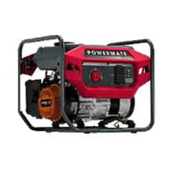 |
| Fig 6: Power Generator |
Thank You for visiting the website. Keep visiting for more Updates.
Frequently Asked Questions
The ATS monitors voltage and frequency to verify acceptable power, then transfers the load. If the ATS does not detect an acceptable power supply, no transfer occurs because this action would not improve power availability to loads. Doing so would leave loads isolated from the normal of the source should acceptable power return.
There are two types of automatic transfer switches, circuit diagram breakers and contactors. The circuit diagram breaker type has two interlocked circuit breakers, so only one breaker could be closed at any anytime.
Unlike a manual transfer switch, automatic transfer switches could be used with permanently installed standby generators. That way, when your power is disrupted or your company is subject to blackouts, your generator will automatically kick on and supply emergency backup power to your building.
For service disconnect of the switches, the amperage must match that of the main breaker in your electrical panel, (it is usually located at the very top of the box.) So, if you have a 200-amp main breaker, you will need a 200-amp automatic transfer of the switch.
Beyond the necessity of maintaining a constant electrical supply, an automatic switch offers the most efficient way to change from utility feed to generator feed. Instead of locating manual switches after the lights go out, businesses could let the changeover happen automatically, the only scenario that wholly exempts a building from the noticeable effects of a power supply outage, allowing the business to carry on as before.
You may like these posts

In this diagram, we connect a total of six 3-pin power sockets

A regulator is a good electric device that controls

This diagram shows how to connect the Full House Wiring Diagram

In this circuit we use a DP MCB, some Single pole

In this diagram we use 2 lights, 2 fans, 1 single-phase energy

phase energy meter to house loads like ( light, fan ), etc.

Post a Comment
Do leave your comments