1 Bulb 3 Switch Controls Connection
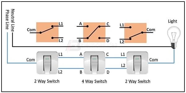
This diagram shows 1 bulb 3 switch controls connection. A Light can be controlled by one switch or more than one switch. In the home, construction is to use 3-way switches. In this diagram, we just describe how to connect 1 light controlled by 3 switches. You need to perfectly make this circuit like in our diagram.
Diagram Image of 1 Bulb 3 Switch Controls Connection wiring
Components Need for this Project:
You can get the components from any of the sites below:
$ads={1}
Read Also:
Components used to make the 1 Bulb 3 Switch Controls Connection:
01. 2 Way Switch
 |
| Fig 2: 2 Way Switch |
02. 4 Way Switch
 |
| Fig 3: 4 Way Switch |
03. Light
 |
| Fig 4: Light |
Thank You for visiting the website. Keep visiting for more Updates.
Frequently Asked Questions
You could wire a 3-way switch as a single pole switch by finding which screw terminals work together. You should use one of the dark-colored screws with one of the light-colored screws. Once you find the 2 screws you want to use so the switch is in the up position, connect your hot wires to those two- screw terminals.
First, we need to input the power supply to DP MCB then from DP MCB to connect the RCCB, and then from RCCB to connect another DP MCB. Then from DP MCB to input phase to the switch, then from the switch to connect all light holders. And lastly, input a neutral of the connection to all light holders from the switch.
Three-way switches are commonly used to control one light fixture from 2- different locations. For example, a long hallway and stairway might use a three-way switch at each end so that lights could be turned on when approaching one end of the hall or stairway or then shut off from the other end.
A three-way incandescent bulb has two filaments designed to produce different amounts of light. The two filaments could be activated separately or together, giving three different amounts of light. One common three-way incandescent bulb is the 50/100/150 W. It has a low-power 50 W filament and a medium-power supply of 100 W filament.
The switch simply opens (off) and closes (on) the connection between the two terminals on the switch. When the switch is on, current flows along the black wire through the switch to the light, and then returns to ground through the white wire to complete the circuit diagram.
You may like these posts

A Light can be controlled by one switch or more than one switch.

The terminal connects to the device to power when

Another DP MCB here connects to SP (Single Pole) Circuit

An automatic switch can change the power source automatically

This diagram shows the Automatic changeover switch for

AC can be operated at any voltage and frequency


Post a Comment
Do leave your comments