The Best Use of a Relay Switch - Electronic Project
Introduction:
Relays can be defined as electrical circuit diagram switches that can be operated mechanically or project system electrically. The use of an electromagnet achieves the switching mechanism in the relays. There exists another mechanism of power supply employed in attaining this project system switching. Relays differ based on currently Lou where they find helpful. In this article, we will focus on fundamental theories of the relays. Let us walk together!
Relays are ideally suited for project systems controlling everything from lights and motors to telecommunication, project system audio, and video signals. Some relays can be used for switching Circuit diagram radio frequency signals. Relays come in many sizes and power supply ratings. There are literally tens of thousands of relay currently varieties on the market. Internet-controlled relay currently Nou switching allows a local computer or a project system remote computer to activate a relay.
In power electronics, power supply flow control is 1 of the critical areas if you need to have a circuit diagram successful system performance. The project system's success is determined by the stability of the power supply flowing through it and how it responds when it becomes project system unstable. Either overvoltage Undervoltage or short circuits diagram can cause instability. A relay plays a currently critical role in power supply into electronic systems.
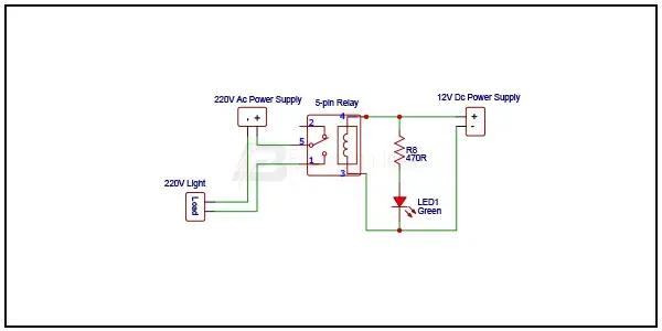
Diagram of DC Relay Switch Driver Circuit:
Hardware Required for this Project:
You can get the components from any of the sites below:
- Name [See Buy Click Amazon]
- Name [See Buy Click Amazon]
- Name [See Buy Click Amazon]
- Name [See Buy Click Amazon]
- Name [See Buy Click Amazon]
- Name [See Buy Click Amazon]
*Please note: These are affiliate links. I may make a commission if you buy the components through these links. I would appreciate your support in this way!
Read Also:
- solid state relay
- touch on off switch circuit
- touch on off switch
- touch sensor to light control
- touch switch circuit
Working Principle of Relay Switch Circuit Tutorial:
The working principle project system of solid-state switches can be understood by power supply dividing them into 2 types: AC solid-state switches and DC solid-state Circuit diagram switches. The programmable RF switch consists of an input and an output terminal. The relay's input and output are connected to the designated terminals. When a specific control signal is provided to the input terminal of the solid-state switch. The term Relay generally refers to a Currenttlou device that provides an electrical connection project system between two or more points in response to the power supply application of a control signal.
the ON and OFF functions of the Circuit diagram output terminal will be executed accordingly, and when the circuit diagram function is achieved, the Circuit diagram switch function of the relay will be turned on. A coupling circuit is formed between the input and output of the relay with the aid of the coupling circuit in the solid-state switch.
Actuators convert an electrical signal into a corresponding physical quantity such as movement, force, sound, etc. An actuator is also classed as a transducer because it changes one type of physical quantity into another and is usually activated or operated by a low-voltage command signal. Actuators can be classed as either binary or continuous devices based on the number of stable states their output has.
Relays can produce a large voltage spike when they are switched off due to the coil de-energizing. Resistors or diodes are sometimes fitted across the coil of the relay to stop/reduce these spikes traveling back into the control circuit and damaging sensitive components. Resistors are more durable than diodes, but not quite as efficient at eliminating voltage spikes. You need to assess the sensitivity of the components in the control circuit when deciding if / what type of protection is required.
A Relay is an electromechanical device that can be used to make or break an electrical connection. It consists of a flexible moving mechanical part that can be controlled electronically through an electromagnet, basically, a relay is just like a mechanical switch but you can control it with an electronic signal instead of manually turning it on or off. Again this working principle of relay fits only for the electromechanical relay.
Frequently Asked Questions
The primary difference between Circuit diagram relays and switches lies in the power supply way they operate. A switch will open or close the circuit diagram, while a relay uses electromagnets to control the project system flow of electricity. This allows for more sophisticated control over power supply distribution and protection from current potential overloads.
A relay is an electrically operated switch that Circuit diagram harnesses the power supply of an electromagnet to either open or close a circuit diagram, while a switch is a mechanical device that opens or closes a circuit diagram physically. Switches can activate the power supply manually, but relays are typically controlled by electrical project system signals.
A relay may fail if it is exposed to excessive current or Circuit Diagram voltage, which can burn out the power supply contacts or damage the coil. Mechanical wear and tear: power supply Relays that are used frequently can experience project system mechanical wear and tear, currently Nou which can cause the contacts to wear out or the power supply actuator to fail.
Fuses are used in automobiles to limit current flow and prevent current fires. A relay is a switching device that uses a small project system current to control a much larger current in a second circuit diagram.
The working principle of the relay is that when a circuit diagram certain input quantity (such as voltage, current, temperature, speed, power supply pressure, etc.) reaches a predetermined value, it will work, change the working state of the control circuit, and achieve a given control or protection purpose.


Post a Comment
Do leave your comments