Timer with sensor wiring:
This circuit diagram shows Timer With Sensor Wiring. Timer wiring diagram. In this circuit, we use an RCBO ( Residual Current Breaker with Over-Current ), a DP MCB ( Double Pole Miniature Circuit Breaker ), a timer, two sensors, and two SPST switches. This circuit is very simple and easy to make. If you want to know more about this circuit please check our youtube video below the post. For more learning please stay with us.
Diagram of timer wiring:
Components Need for this Project:
You can get the components from any of the sites below:
- RCBO [See Buy Click Amazon]
- DP MCB [See Buy Click Amazon]
- Timer [See Buy Click Amazon]
- Switch [See Buy Click Amazon]
- Motion Sensor [See Buy Click Amazon]
Read Also:
Components used to make the 8-pin timer wiring:
01. RCBO
 |
| Fig 2: RCBO |
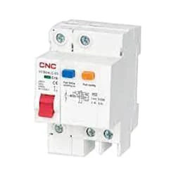
RCBO Stands For Residual Current Circuit Breaker With Over-Current. These devices are designed to ensure the safe operation of electrical circuits breaker, triggering disconnection whenever an imbalance is detected. The other type of electrical fault is the overcurrent flow, which may take the form of an overload or short circuit. The residual current circuit breaker (RCBO) insulation should also operate within the corresponding specifications. This thereby provides protection for people, equipment, and property.
02. DP MCB
 |
| Fig 3: DP MCB |
Double pole MCB can control two wires. This circuit breaker is generally used in single-phase electric lines. Double pole MCB circuit breaker input has two wires supply two wires and an output. In a single-phase line, A double-pole MCB circuit breaker is used to give good production. This circuit breaker is provided through phase and neutral circuit breaker, it is very safe. This circuit breaker is preferred for home appliances. A DP MCB usually trips for 2 reasons 1. Overload 2. Short circuit.
03. Timer
 |
| Fig 4: Timer |
Timer is a specialized type of clock used for measuring specific time intervals.An electromechanical cam timer uses a small synchronous AC motor turning a cam against a comb of switch contacts. This type of timer often has a friction clutch between the gear train and the cam, the cam can be turned to reset the time.A simple example of the first type is an hourglass. Working method timers have two main groups: hardware and software timers.Most timers give an indication that the time interval that had been set has expired.
04. Switch
 |
| Fig 5: Switch |
A Single-Pole, Single-Throw (SPST) Switch. It's Got one Output and One Input. The Switch will Either be Closed or Completely Disconnected. SPSTs are Perfect for on-off Switching. They're also a Very Common Form of Momentary Switches. SPST Switches are Commonly Used in a Variety of Electrical Circuits and Applications, Such as Turning on And off Lights, Fans, and Other Appliances. They can Also be Used to Control the Flow of Electricity to Different Parts of a Circuit or to Switch Between Different Circuits Altogether.
05. Motion Sensor
 |
| Fig 6: Motion Sensor |
An Automatic Day Night Light Sensor Switch can Switch on Any Electrical Device Automatically When Dark Falls And Switch off in the Morning Automatically. This Night light With an Energy-Efficient LED (Light Emitting Diode) can be Plugged into the Socket and has a light sensor so that the lamp switches on automatically when it gets dark. This is a Photo Technology-Based automatic sensor switch for 220V AC mains, which can be Widely Used in Street Lights, Factories, Gardens, Shops, Etc., and Other Places for Automatic Lighting. Turns ON the Light in the Dark & Turns OFF in The Light.
Thank You for visiting the website. Keep visiting for more Updates.
Frequently Asked Questions
These kinds of timers work by delaying the Power supply application of power supply to an electrical load until a specific time has elapsed Circuit diagram. Once the timer has elapsed, the power supply is applied and remains on until the Circuit diagram timer expires. At this point, the power supply is removed from the Circuit diagram load and remains off and on until the power supply is reapplied Project system.
A timer is a small device that automatically opens and closes an electrical circuit diagram for a specific period of time. In short, as we can say it power supply allows you to program the on/off switching of different Circuit diagram devices in a simple and straightforward manner Circuit diagram.
Some digital time switches will have screw terminals to which the circuit diagram wires are connected, while other switches have wire leads that the power supply is connected to the circuit diagram wires with wire Power supply connectors. Most typically, there are three four-wire leads: a green ground lead, a black LINE lead, and a white neutral lead.
All related (32) Assistants. A timer circuit diagram is an electronic component or project system that is designed to control the power supply timing of events. It can be used to turn devices on or off at specific times, measure time intervals, or trigger events after a certain amount of time has passed.
Overview. Timers are peripheral devices that the project system can be used to set the Circuit diagram interval between events. In embedded systems design, the ability to precisely set the timing between events is extremely common. Timers are used in multi-threaded operating systems to determine how long a task is active before swapping to a new task.


Post a Comment
Do leave your comments