Timer In Light wiring diagram:
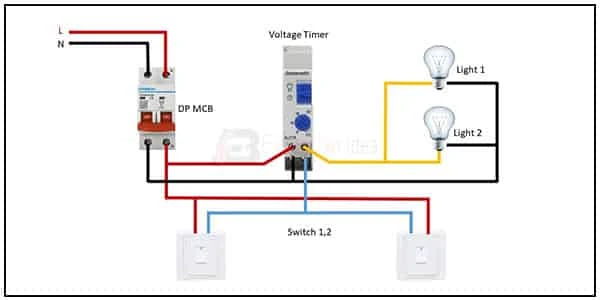
This circuit diagram shows Timer In Light Wiring Diagram. Digital timer switch wiring diagram. In this circuit, we use DP MCBs ( Double Pole Minature Circuit Breaker ), a voltage timer, two lights, and two switches. This circuit is very simple and easy to make. If you want to know more about this circuit please check our youtube video below the post. For more learning please stay with us.
Diagram of timer in light wiring:
Components Need for this Project:
You can get the components from any of the sites below:
- DP MCB [See Buy Click Amazon]
- Timer [See Buy Click Amazon]
- Light [See Buy Click Amazon]
- Switch [See Buy Click Amazon]
Read Also:
Components used to make the digital timer switch wiring:
01. DP MCB
 |
| Fig 2: DP MCB |
Double pole MCB can control two wires. This circuit breaker is generally used in single-phase electric lines. Double pole MCB circuit breaker input has two wires supply two wires and an output. In a single-phase line, A double-pole MCB circuit breaker is used to give good production. This circuit breaker is provided through phase and neutral circuit breaker, it is very safe. This circuit breaker is preferred for home appliances. A DP MCB usually trips for 2 reasons 1. Overload 2. Short circuit.
02. Timer
 |
| Fig 3: Timer |
Timer is a specialized type of clock used for measuring specific time intervals.An electromechanical cam timer uses a small synchronous AC motor turning a cam against a comb of switch contacts. This type of timer often has a friction clutch between the gear train and the cam, the cam can be turned to reset the time.A simple example of the first type is an hourglass. Working method timers have two main groups: hardware and software timers.Most timers give an indication that the time interval that had been set has expired.
03. Light
 |
| Fig 4: Light |
CFLs work in a completely different way from ordinary lamps, they work by using a different process called fluorescence rather than generating light from heat. A typical light bulb wastes 90% of energy and converts only 10% of energy into light, this is where CFL has the biggest advantage. CFL- Curved or conical glass tube filled with argon and a small amount of mercury vapor. The inner wall of the glass is coated with fluorescent material. CFL- It is manufactured using the principle of creating fluorescent light. CFL- Originally white in color but now the construction and use of CFLs producing colored light has become popular.
04. Switch
 |
| Fig 5: Switch |
A Single-Pole, Single-Throw (SPST) Switch. It's Got one Output and One Input. The Switch will Either be Closed or Completely Disconnected. SPSTs are Perfect for on-off Switching. They're also a Very Common Form of Momentary Switches. SPST Switches are Commonly Used in a Variety of Electrical Circuits and Applications, Such as Turning on And off Lights, Fans, and Other Appliances. They can Also be Used to Control the Flow of Electricity to Different Parts of a Circuit or to Switch Between Different Circuits Altogether.
Thank You for visiting the website. Keep visiting for more Updates.
Frequently Asked Questions
Timer Switches Power supply automatically turns lights off and on, making them a convenient and energy-saving Circuit diagram option. Some timer switches can be used for added home safety by automatically turning lights on when dark, so you arrive at a well-lit home, or to make a home look “lived-in” while residents are away.
Plug the timer into an electrical outlet and connect your light project system. Put the programmed timer into any free Circuit diagram electrical socket. Plug the power cord from a lamp or other light fixture into an outlet on the timer and turn the light's power switch on so the timer will turn it on and off at the times you programmed.
Many electrical timers require a neutral so that the Power supply switch can be powered without sending the power supply to the load. If you do not have a neutral at the Circuit diagram switch box it means that the power supply source (line) does not come into that box and you are just switching the Currenttlou hot from another source.
For example, when you schedule your television to go off after two hours, you immediately turn it on, and the oscillator starts pulsating. Once these pulses equal 2 hours, the Circuit diagrams timer switch circuit diagram releases a bolt of energy that will turn off and on the television.
A light timer is an electrical circuit diagram with a built-in clock. Acting as a communicator and between the power supply source and the light, the Circuit diagram timer turns lights on and off based on the Power supply times you set. Available in a variety of sizes,as these devices come equipped with controls ranging from circular diagrams dials to digital settings.


Post a Comment
Do leave your comments