Switch for Housing connection:
This diagram shows Make and switch for housing connection. the house line 3 types of wires used in house hold circuit are earth wire, Live wire, and Neutral wire. House in copper wires/cables are the best electric wire. earthing is used to protect you from an electric shock for line. House wiring for cable size 1.5sq, 2.5sq, 4sq, & 6sq etc using cable best use.
Diagram of house wiring:
Components Need for this Project:
You can get the components from any of the sites below:
- RCCB [See Buy Click Amazon]
- RCBO [See Buy Click Amazon]
- Light [See Buy Click Amazon]
- Switch [See Buy Click Amazon]
Read Also:
Components used to make the basic house wiring:
01. RCCB
 |
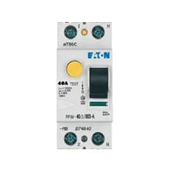
| Fig 2: RCCB |
The RCCB (Residual Current Circuit Breaker) or RCCB is an electrical protective device.Residual Current Circuit Breaker is specially designed to protect the electrical circuit against earth fault and human from electrical shock.In this, under normal condition the load is always connected in between the phase terminal to neutral terminal, hence the flow of phase current is equal to neutral current.Earth fault or fault in a power system can cause excess heating, more power consumption, burning or fire, etc. So, protection against earth leakage is very important.
02. RCBO
 |
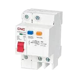
| Fig 3: RCBO |
RCBO Stands For Residual Current Circuit Breaker With Over-Current. These devices are designed to ensure the safe operation of electrical circuits breaker, triggering disconnection whenever an imbalance is detected. The other type of electrical fault is the overcurrent flow, which may take the form of an overload or short circuit. The residual current circuit breaker (RCBO) insulation should also operate within the corresponding specifications. This thereby provides protection for people, equipment, and property.
03. Light
 |
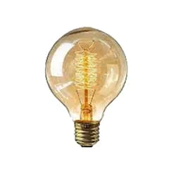
| Fig 4: Light |
CFLs work in a completely different way from ordinary lamps, they work by using a different process called fluorescence rather than generating light from heat. A typical light bulb wastes 90% of energy and converts only 10% of energy into light, this is where CFL has the biggest advantage. CFL- Curved or conical glass tube filled with argon and a small amount of mercury vapor. The inner wall of the glass is coated with fluorescent material. CFL- It is manufactured using the principle of creating fluorescent light. CFL- Originally white in color but now the construction and use of CFLs producing colored light has become popular.
04. Switch
 |
| Fig 5: Switch |
A Single-Pole, Single-Throw (SPST) Switch. It's Got one Output and One Input. The Switch will Either be Closed or Completely Disconnected. SPSTs are Perfect for on-off Switching. They're also a Very Common Form of Momentary Switches. SPST Switches are Commonly Used in a Variety of Electrical Circuits and Applications, Such as Turning on And off Lights, Fans, and Other Appliances. They can Also be Used to Control the Flow of Electricity to Different Parts of a Circuit or to Switch Between Different Circuits Altogether.
Thank You for visiting the website. Keep visiting for more Updates.
Frequently Asked Questions
Your main circuit diagram breaker is on your electrical service panel box Power supply. If you are wondering where it is located in your current house, look for the electrical Circuit diagram service panel box in your Project system basement or garage. Sometimes they are near your water heater or near the Circuit diagram laundry.
To make an electric wiring diagram, you simply draw all the symbols of the components that you want to use in your circuit… Then once the components are drawn you will need to connect each of those electrical components, the way you envisioned and designed how the circuit will work using those components.
The most commonly used wiring method in house wiring is non-metallic sheathed cable, also known as Romex cable. This type of cable consists of two or more insulated conductors and a bare ground wire enclosed in a plastic sheath.
The switch simply opens (off and on) or closes (on) the connection between the 2 terminals on the Circuit diagram switch. When the switch is on and on, current flows along the project system black wire through the switch to the light, and then returns to the ground through the white wire to complete the circuit diagram.
A Project system wiring Circuit diagram is exactly what it sounds like – a diagram of the wiring required for a Project system. During the design phase of any aircraft, as a wiring diagram is developed to show how the Power supply electrical wires are interconnected between the various components in each system.


Post a Comment
Do leave your comments