SPD with rccb wiring:
This circuit diagram shows spd with the RCCB wiring diagram. Surge protector wiring diagram. In this circuit, we use four DP MCBs ( Double Pole Minature Circuit Breaker ), an SPD ( Surge Protection Device ), and an RCCB ( Residual Current Circuit Breaker ). This circuit is very simple and easy to make. If you want to know more about this circuit please check our youtube video below the post. For more learning please stay with us.
Diagram of surge protector wiring:
Components Need for this Project:
You can get the components from any of the sites below:
Read Also:
Components used to make the Surge protector wiring:
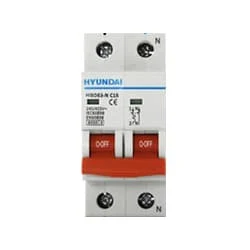
01. DP MCB
 |
| Fig 2: DP MCB |
Double pole MCB can control two wires. This circuit breaker is generally used in single-phase electric lines. Double pole MCB circuit breaker input has two wires supply two wires and an output. In a single-phase line, A double-pole MCB circuit breaker is used to give good production. This circuit breaker is provided through phase and neutral circuit breaker, it is very safe. This circuit breaker is preferred for home appliances. A DP MCB usually trips for 2 reasons 1. Overload 2. Short circuit.
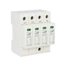
02. SPD
 |
| Fig 3: SPD |
A surge protection device (SPD) or more commonly a surge protector is a device used to protect electronic devices from power surges or transient voltages. A surge protective device is a protective device that limits transient voltages or limits surge current. Surge Protective Devices are Used to Protect Sensitive Electronic Equipment Connected to the Installation such as Computers, Televisions, Washing Machines, and Safety Circuits such as fire Detection Systems and Emergency Lighting. Equipment with Sensitive Electronic Circuitry may be Vulnerable to Damage by Transient Overvoltages.
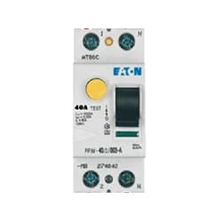
03. RCCB
 |
| Fig 4: RCCB |
The RCCB (Residual Current Circuit Breaker) or RCCB is an electrical protective device.Residual Current Circuit Breaker is specially designed to protect the electrical circuit against earth fault and human from electrical shock.In this, under normal condition the load is always connected in between the phase terminal to neutral terminal, hence the flow of phase current is equal to neutral current.Earth fault or fault in a power system can cause excess heating, more power consumption, burning or fire, etc. So, protection against earth leakage is very important.
Thank You for visiting the website. Keep visiting for more Updates.
Frequently Asked Questions
Short direct connections are best. SPDs should be connected through an appropriately rated circuit breaker, not into the main lugs of the panel. Where circuit breakers are unavailable or impractical, a fused disconnect switch should be used to connect to the lines and facilitate servicing of the SPD.
These Type 3 Surge Protection Devices have a low discharge capacity. They must therefore mandatorily be installed as a supplement to Type 2 Surge Protection Devices and in the vicinity of sensitive loads. Type 3 SPD is characterized by a combination of voltage waves (1.2/50μs) & current waves (8/20μs).
Type 1 SPD is characterized by a 10/350 µs current wave. Type 2 SPD. The Type 2 SPD is the main protection system for all low-voltage electrical installations. Installed in each electrical switchboard, it prevents the spread of overvoltages in the electrical installations and protects the loads.
In the simplest terms, SPDs are intended to limit transient overvoltages with the goal of preventing equipment damage and downtime due to transient voltage surges reaching the devices they protect.
Surge protection should always be installed at the main service entrance. It is best to use cascaded protection for the sub-panels and equipment, especially in larger facilities where the critical loads are far away from the main. Knowledge is power. Theoretically, any size SPD can be used in a system.


Post a Comment
Do leave your comments