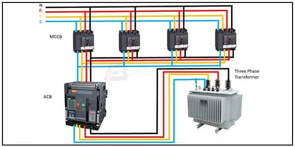
MCCB Shunt trip wiring:
This diagram shows how to make a 3 mccb shunt trip wiring diagram. In this circuit, we use a 3-phase transformer, four MCCBs ( Molded Case Circuit Breakers), and an ACB ( Air Circuit Breaker ), First, we need to connect all MCCBs with the Power source then connect the ACB and the 3-phase transformer.
Diagram of MCCB shunt trip wiring:
Components Need for this Project:
You can get the components from any of the sites below:
Read Also:
Components used to make the MCCB shount trip diagram:
01. MCCB
 |
| Fig 2: MCCB |
MCCB (Molded Case Circuit Breakers) is a Required Component of Electrical Systems, Providing Overload Protection And Short-Circuit Protection. Circuit breakers are electrical devices that offer protection against fault currents. Molded Case Circuit Breakers (MCCB) or Molded Case Circuit Breakers Use air as The Dielectric Medium to Break a Circuit. Air Has a Low Dielectric Strength as Opposed to Other Mediums Which is why it is Used for Protection in low-Voltage Circuits. In Most Cases, Molded Case Circuit Breakers are installed in the Main Power Distribution Board of a Facility, Allowing the system to be easily shut Down When Necessary.
02. 3 Phase Transformer
 |
| Fig 3: 3 phase Transformer |
Three-phase Transformers are Passive Machines That Pass Electric Energy Between Circuits. In the Secondary Circuit, a Magnetic flux Induces an Electromotive Force (emf), Thus Stepping up (increasing) or Stepping down (decreasing) Voltages Without Altering the Frequency. There are Different Kinds of Electrical Systems and Therefore Transformers have to Operate Alongside Compatible Systems. A 3-phase Transformer Works with 3 Phase AC Electrical System to Provide Consumers With Stable and Device-Safe Electricity.
Thank You for visiting the website. Keep visiting for more Updates.


Post a Comment
Do leave your comments