key Switch with Light wiring:
This diagram shows how to make Key Switch With Light Wiring. In this circuit, we use two CFL Lights, a magnetic contactor, a DP MCB ( Double Pole Minature Circuit Breaker ), and a Key switch. First, we need to connect the DP MCB with the power source and then connect them with a light and key switch. Now it's ready for use.
Diagram of Key Switch with light wiring:
Components Need for this Project:
You can get the components from any of the sites below:
- DP MCB [See Buy Click Amazon]
- Contactor [See Buy Click Amazon]
- Key Switch [See Buy Click Amazon]
- Light [See Buy Click Amazon]
Read Also:
Components used to make the key switch with light wiring:
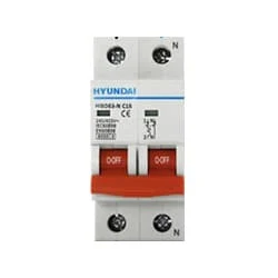
01. DP MCB
 |
| Fig 2: DP MCB |
Double pole MCB can control two wires. This circuit breaker is generally used in single-phase electric lines. Double pole MCB circuit breaker input has two wires supply two wires and an output. In a single-phase line, A double-pole MCB circuit breaker is used to give good production. This circuit breaker is provided through phase and neutral circuit breaker, it is very safe. This circuit breaker is preferred for home appliances. A DP MCB usually trips for 2 reasons 1. Overload 2. Short circuit.
02. Contactor
 |
| Fig 3: Contactor |
A magnetic contactor is an electrical device used for load control, automation, and protection. It is much like a magnetic reel. However, relays are generally used for low power and voltage, on the other hand, when we think of high power, these heavy-duty contractors only come to mind. It basically works by switching the load on and off. It has 3 terminals whose inputs are denoted as L1, L2, L3, and outputs as T1, T2, and T3. The circuit of the load is made in automation mode or protection using auxiliary contacts. It has two types of terminals. 1) Normally Open (NO). 2) Normally Closed (NC)
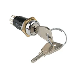
03. Key Switch
 |
| Fig 4: Key Switch |
The system a key switches are to lock the door of a building. A Contactor to key switch to control wiring. A key switch is a SDB that allows you to turn something on-off by using a key switch. Key switches system are usually used as part of a larger system, such as a security system or an electric lock using.
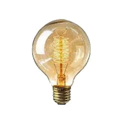
04. Light
 |
| Fig 5: Light |
CFLs work in a completely different way from ordinary lamps, they work by using a different process called fluorescence rather than generating light from heat. A typical light bulb wastes 90% of energy and converts only 10% of energy into light, this is where CFL has the biggest advantage. CFL- Curved or conical glass tube filled with argon and a small amount of mercury vapor. The inner wall of the glass is coated with fluorescent material. CFL- It is manufactured using the principle of creating fluorescent light. CFL- Originally white in color but now the construction and use of CFLs producing colored light has become popular.
Thank You for visiting the website. Keep visiting for more Updates.
Frequently Asked Questions
This test key switch is for testing emergency Power Supply lighting in a quick and convenient manner. Simply push the key into the Circuit Diagram switch, this will interrupt the power supply, testing the Currenttlou emergency lighting in the Circuit diagram process. Numerous light fittings can be tested quickly in a cost-effective way.
The Circuit diagram short answer is - Yes, as you should! Common smart switches require a neutral wire. So before you are going to buy a large amount of smart light switches, make sure your walls have the neutral wire installed.
Smart switches are designed as direct Circuit diagram replacements for traditional built-in power supply switches. Yes, you can still turn your lights on and off, just as you always did, but these smart switches provide you with much greater control over your home's lighting, as well as fans and hardwired appliances.
A single-pole switch is the most common type of light switch that you'll find in a home. This type of switch controls a single light fixture or a power supply series of fixtures from 1 location. It has2 brass terminal screws and a Circuit diagram toggle labeled “ON” and “OFF.”
A single pole switch has one input and 1 output, it has 2 states; “on” or “off”. They can be wired to either project system normally open or normally closed and can be either latching or Circuit diagram momentary. There are two types of single pole switches, these are “single-pole, single throw” and “single pole double throw”.


Post a Comment
Do leave your comments