Garden light contactor wiring:
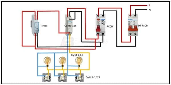
This diagram shows how to make garden lights contactor wiring. In this circuit, we use a timer a contactor, a RCCB, a DP MCB., and 3 CFL Lights. First, we need to connect the DP MCB ( Double Pole Minature Circuit Breaker ), then connect the RCCB with the DP MCB, then connect the contactor with the RCCB then connect the timer light and switch with the contactor.
Diagram of Garden light contactor wiring:
Components Need for this Project:
You can get the components from any of the sites below:
- DP MCB [See Buy Click Amazon]
- RCCB [See Buy Click Amazon]
- Contactor [See Buy Click Amazon]
- Timer [See Buy Click Amazon]
- Light [See Buy Click Amazon]
- Switch [See Buy Click Amazon]
Read Also:
Components used to make the Single phase garden lights contactor wiring:
01. DP MCB
 |
| Fig 2: DP MCB |
Double pole MCB can control two wires. This circuit breaker is generally used in single-phase electric lines. Double pole MCB circuit breaker input has two wires supply two wires and an output. In a single-phase line, A double-pole MCB circuit breaker is used to give good production. This circuit breaker is provided through phase and neutral circuit breaker, it is very safe. This circuit breaker is preferred for home appliances. A DP MCB usually trips for 2 reasons 1. Overload 2. Short circuit.
02. RCCB
 |
| Fig 3: RCCB |
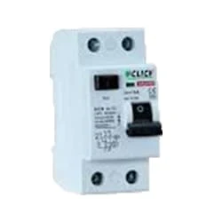
The RCCB (Residual Current Circuit Breaker) or RCCB is an electrical protective device. A residual Current Circuit Breaker is specially designed to protect the electrical circuit against earth faults and humans from electrical shock. In this, under normal conditions the load is always connected between the phase terminal to the neutral terminal, hence the flow of the phase current is equal to the neutral current. Earth fault or fault in a power system can cause excess heating, more power consumption, burning or fire, etc. So, protection against earth leakage is very important.
03. Contactor
 |
| Fig 4: Contactor |
A magnetic contactor is an electrical device used for load control, automation, and protection. It is much like a magnetic reel. However, relays are generally used for low power and voltage, on the other hand, when we think of high power, these heavy-duty contractors only come to mind. It basically works by switching the load on and off. It has 3 terminals whose inputs are denoted as L1, L2, L3, and outputs as T1, T2, and T3. The circuit of the load is made in automation mode or protection using auxiliary contacts. It has two types of terminals. 1) Normally Open (NO). 2) Normally Closed (NC)
04. Timer
 |
| Fig 5: Timer |
Timer is a specialized type of clock used for measuring specific time intervals.An electromechanical cam timer uses a small synchronous AC motor turning a cam against a comb of switch contacts. This type of timer often has a friction clutch between the gear train and the cam, the cam can be turned to reset the time.A simple example of the first type is an hourglass. Working method timers have two main groups: hardware and software timers.Most timers give an indication that the time interval that had been set has expired.
05. Light
 |
| Fig 6: Light |
CFLs work in a completely different way from ordinary lamps, they work by using a different process called fluorescence rather than generating light from heat. A typical light bulb wastes 90% of energy and converts only 10% of energy into light, this is where CFL has the biggest advantage. CFL- Curved or conical glass tube filled with argon and a small amount of mercury vapor. The inner wall of the glass is coated with fluorescent material. CFL- It is manufactured using the principle of creating fluorescent light. CFL- Originally white in color but now the construction and use of CFLs producing colored light has become popular.
06. Switch
 |
| Fig 7: Switch |
A Single-Pole, Single-Throw (SPST) Switch. It's Got one Output and One Input. The Switch will Either be Closed or Completely Disconnected. SPSTs are Perfect for on-off Switching. They're also a Very Common Form of Momentary Switches. SPST Switches are Commonly Used in a Variety of Electrical Circuits and Applications, Such as Turning on And off Lights, Fans, and Other Appliances. They can Also be Used to Control the Flow of Electricity to Different Parts of a Circuit or to Switch Between Different Circuits Altogether.
Thank You for visiting the website. Keep visiting for more Updates.
Frequently Asked Questions
Operating Principle of a Contactor:The current passing through the contactor excites the electromagnet. The excited electromagnet produces a magnetic field, causing the contactor core to move the armature. A normally closed (NC) contact completes the circuit between the fixed contacts and the moving contacts.
The contactor's rated voltage should equal the maximum voltage of the controlled circuit. Likewise, ensure that the rated current is higher than that of the controlled circuit. To maintain high-frequency equipment, such as motors, select a higher-rated contactor to ensure efficient operation and increased life.
Typically, contactor terminals will be silver plated, or nickel plated, copper or brass. So, according to Table 2, the maximum permissible temperature rise is 70°K [above ambient]. The operating temperature range for this contactor is -55°C to +85°C which means the terminals could be at 170°C when fully loaded!
Contactors are designed and built to handle much higher power switching applications than control relays. Relays are typically reserved for use with loads of around 5A-15A, and they are most often rated for 10A or less. Contact standards. Contactors are almost always set up in a normally open (NO) configuration.
The main difference between a contactor and a relay is their load capacity. Contactors are designed to handle high currents, typically above 15 amps, while relays are more suitable for low to medium current loads, usually below 15 amps.


Post a Comment
Do leave your comments