Voltmeter Selector Switch connetion:
This diagram shows How to make Voltmeter Selector switch connection diagram. Voltmeter Selector Switch Wiring. In this circuit, we use a TP MCB ( Tripple Pole Miniature Circuit Breaker ), a two-position selector switch, and a single-phase volt meter. This circuit is very simple and very easy to make. If you want to know more about this circuit please stay with our website and check our youtube video below the post.
Diagram of voltmeter switching wiring:
Components Need for this Project:
You can get the components from any of the sites below:
Read Also:
Components used to make the voltmeter selector switching:
01. TP MCB
 |
| Fig 2: TP MCB |
Three wires can be controlled by a triple pole MCB. Triple pole MCB circuit breakers are generally used in three-phase lines. A triple-pole MCB circuit breaker has three wires at its input and three wires at its output. But one can use this circuit breaker in a single-phase line. TP MCB widely used in industries. The reason is that it has three poles. And this TP circuit breaker is used to provide three-phase and three-phase connections. A neutral is not normally used in three-phase lines. But a 4-pole MCB circuit breaker is used if needed.
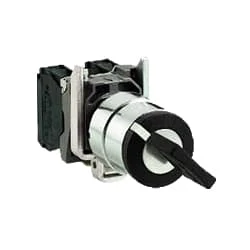
02. Selector Switch
 |
| Fig 3: Selector Switch |
Selector Switches Can be Rotated left, Right, or in The Center in Order to Open or Close The Electrical Contacts. The Function of a Selector Switch is To Control Devices as well as Switch Between a Minimum of Two or More Circuits. The perfect Use For a Selector Switch is When Used for Controlling an Output of a Device. Selector Switches Come as a Complete Unit Often listed as a Terminal Block Meaning the Selector Switch is a Complete Block Which Makes it Simple And easy to Install.
03. Voltmeter
 |
| Fig 4: Voltmeter |
An instrument that measures the potential difference between any two points in a circuit directly in volts is called a voltmeter. To Measure the Potential Difference Between two Points in the Circuit, the Voltmeter Should be Connected in Parallel with those two points. The working common volt meter and ammeter are similar and work on the same principle. Current flows through the coil of the voltmeter at a rate proportional to the voltage and the reading are obtained. The internal resistance of this meter is very high. The coil of a volt meter is made up of many strands of thin wire.
Thank You for visiting the website. Keep visiting for more Updates.
Frequently Asked Questions
The voltage and selector switch on some electrical devices allows the user to adjust the power supply voltage to match the electrical Project system of different countries. This is particularly useful for travelers or for devices that are intended for use in multiple regions with different voltage standards.
An automatic phase selector switch is a device that performs the function of overvoltage protection as well as voltage in phase availability and quality control. The device automatically selects the Circuit diagram nearest phase priority and couples a single-phase load to it.
A typical application as a voltage selection relay is the power supply automatic connection of metering equipment to an alternative power supply if the normal or preferred supply fails. As a fuse failure relay, it will monitor the output of a voltage transformer and give an alarm or disconnect protection circuits diagram for VT fuse failure.
In CSS, selectors are used to target the HTML elements on our web pages that the Circuit diagram we want to style. There are a wide variety of CSS selectors available,as allowing for fine-grained precision when selecting elements to style.
Place one lead on the center or COMMON terminal. The other lead on one of the output terminals and toggle the switch to test. If you have continuity in one switch position the switch is fine. Repeat on the other output lead to confirm the selector switch is fully functional.


Post a Comment
Do leave your comments