Timer using switch wiring:
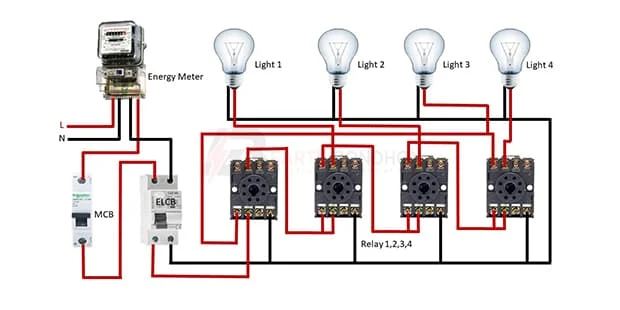
This diagram shows how to make a Timer using switch wiring. Wiring a timer switch diagram. In this circuit, we use four 8-pin relays, an SP MCB (Single Pole Miniature Circuit Breaker ), an ELCB ( Earth Leakage Circuit Breaker ), and four lights. Here we need to connect all components like in our diagram. Now this circuit is ready for use. This circuit is very simple and easy to make. If you want to know more about this circuit please check our youtube video below the post.
Diagram of timer switch wiring:
Components Need for this Project:
You can get the components from any of the sites below:
- Energy Meter [See Buy Click Amazon]
- SP MCB [See Buy Click Amazon]
- ELCB [See Buy Click Amazon]
- Light [See Buy Click Amazon]
- Relay [See Buy Click Amazon]
Read Also:
Components used to make the timer switching wiring:
01. Energy Meter
 |
| Fig 2: Energy Meter |
The measuring device with the help of which the electric power or energy of a circuit is measured is called Energy Meter (Energy Meter). Also called a watt-hour or kilowatt-hour meter. For home appliances, we used a single-phase energy meter. The single-phase energy meter is directly connected between the line and the load. Both coils produce their magnetic fields, when the meter is connected to the supply line, and the load. Energy meters are used in homes and in industrial applications where we want to found that how much energy is being consumed by home appliances and electrical equipment.
02. SP MCB
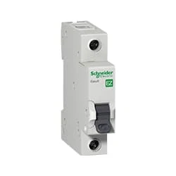 |
| Fig 3: SP MCB |
MCB SP means single pole it protects only one phase switching. MCB (Miniature Circuit Breaker) Curswitch is the most basic general-purpose switch that you use to control a light or another device from one location. These Switches Have Two Brass-Colored Screw Terminals Connected to the hot Power Source Wires. (MCB) For any Distribution Board, the Protection System Must be Used in The Incomer. Phase and Neutral Single Phase Supply to break. 120-volt circuits, 15-20 amp single pole breaker is typically used.
03. ELCB
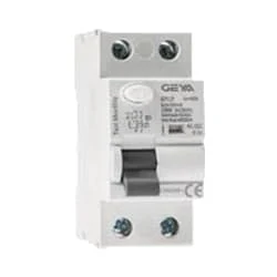 |
| Fig 4: ELCB |
An earth-leakage circuit breaker (ELCB) is a safety device used in electrical installations with high Earth impedance to prevent shock.Generally, the current sensing devices termed Residual current Circuit Breaker (RCCB), and voltage detecting devices named Earth Leakage Circuit breaker Earth-Leakage Circuit Breaker (ELCB). For several years, both the voltage and current operated ELCBs were both referred to as ELCB (Earth-Leakage Circuit Breaker) due to their simple name to remember. But the applications of these 2 devices gave growth to the significant mix-up in the electrical industry.
04. Light
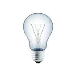 |
| Fig 5: Light |
CFLs work in a completely different way from ordinary lamps, they work by using a different process called fluorescence rather than generating light from heat. A typical light bulb wastes 90% of energy and converts only 10% of energy into light, this is where CFL has the biggest advantage. CFL- Curved or conical glass tube filled with argon and a small amount of mercury vapor. The inner wall of the glass is coated with fluorescent material. CFL- It is manufactured using the principle of creating fluorescent light. CFL- Originally white in color but now the construction and use of CFLs producing colored light has become popular.
05. Relay
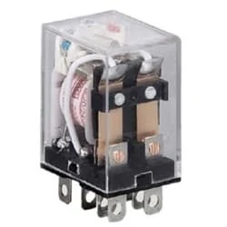 |
| Fig 6: Relay |
This relay is known as 8 pin relay because it has 8 terminals. When coil power is supplied. A magnetic induction is created due to which the connected sheet of the Com part moves towards the NO part changing to NO-NC. The former NC region loses conductivity and becomes NO. Thus, as long as power is supplied to the coil, the NO and NC positions will remain in the alternating state, and when the power is removed from the coil, it will return to its original position. This is basically how a relay switch works.
Thank You for visiting the website. Keep visiting for more Updates.
Frequently Asked Questions
To set the timer accurately, use your fingers to grasp the Circuit diagram outer ring of this dial and rotate it clockwise until the power supply arrow on the inner circle of the Currenttlou timer aligns with the current time. Press the button next to the hour and a fraction of the hour at which you want the light to turn on.
Manual timers are typically set by turning a dial to the Circuit diagram time interval desired, turning the dial stores and energy in a mainspring to run the power supply mechanism. They function similarly to a mechanical alarm clock, as the energy in the mainspring Project system causes a balance wheel to rotate back and forth project system.
A digital timer switch, also known as an electronic timer switch, seamlessly integrates semiconductor components for precise timing and a digital display format to present timing information in a user-friendly manner.
A light timer is an electrical circuit diagram with a built-in clock. Acting as a communicator between the power source and the light, the timer turns lights on and off based on the times you set. Available in a variety of sizes, these devices come equipped with Project system controls ranging from circular dials to digital current settings.
The first thing you should do is make sure that your lighting power supply timer is plugged into a working outlet or socket Circuit diagram. You can use a multimeter, a voltage, and tester, or another device to check the voltage and current of the power supply source. If the outlet or socket is faulty, replace it or use a different one.

Post a Comment
Do leave your comments