Timer Relay Wiring diagram:
This diagram shows how to make Time Relay Wiring Diagram. Digital Timer connection diagram. In this circuit, we use a DP MCB ( Double Miniature Circuit Breaker ), a timer, an NC/NO switch, and an exhaust fan. First, we need to connect DP MCB with power, then connect the timer, then connect the NO/NC Switch, and exhaust fan with the connection. Now this circuit is ready for use. If you want to know more about this circuit please stay with our youtube video below this post.
Diagram of Timer connection wiring:
Components Need for this Project:
You can get the components from any of the sites below:
- DP MCB [See Buy Click Amazon]
- Extractor Fan [See Buy Click Amazon]
- Timer [See Buy Click Amazon]
- NO Switch [See Buy Click Amazon]
- NC Switch [See Buy Click Amazon]
Read Also:
Components used to make the Timer realy connection:
01. DP MCB
 |
| Fig 2: DP MCB |
Double pole MCB can control two wires. This circuit breaker is generally used in single-phase electric lines. Double pole MCB circuit breaker input has two wires supply two wires and an output. In a single-phase line, A double-pole MCB circuit breaker is used to give good production. This circuit breaker is provided through phase and neutral circuit breaker, it is very safe. This circuit breaker is preferred for home appliances. A DP MCB usually trips for 2 reasons 1. Overload 2. Short circuit.
02. Extractor Fan
 |
| Fig 3: Extractor Fan |
An exhaust fan is a device that removes stale air from a room. It is a small fan that has good speed and removes bad air, it is used in a kitchen or small house, mosque, hall, etc. It is used in one or three-phase lines. The vacuum cleaner can be easily controlled. Ventilation is very important as it reduces/eliminates odor and humidity problems throughout the home. Modern building materials may not provide enough space for them to have ventilation. It is important to have good ventilation in areas such as the kitchen and the bathroom. Since most of the activities that take place in these buildings produce bad air quality that must be eliminated. A vacuum cleaner is the most effective tool or device for this job.
03. Timer
 |
| Fig 4: Timer |
Timer is a specialized type of clock used for measuring specific time intervals.An electromechanical cam timer uses a small synchronous AC motor turning a cam against a comb of switch contacts. This type of timer often has a friction clutch between the gear train and the cam, the cam can be turned to reset the time.A simple example of the first type is an hourglass. Working method timers have two main groups: hardware and software timers.Most timers give an indication that the time interval that had been set has expired.
04. NO Switch
 |
| Fig 5: NO Switch |
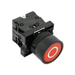
The operator switch has its contact in Normally Open condition. To make Ladder Logic you need to understand NO contact. A Classic Switch has one Input And one Output. In "No Switch," YoungBoy Raps About Ammunition, Murder, Firearms, and Firearm Attachments Such as a Switch. The contact of the switch whose contact is already open is NO. That is enough to understand. no switch in a circuit, then the circuit will not function as intended. to write a program such that when the red light is on, This switch is now in normally open condition. When you push the switch it will close and the red light will turn on.
05. NC Switch
 |
| Fig 6: NC Switch |
Indicates the contacts of switches or automatic actionable devices. Simply put, the push switches, magnetic contactors, and relays that we use in the factory Normally have Close Contact exists. At this moment the switch will be in normally closed condition. Because already he is sitting close. When turned off the contact will open. To make ladder logic you need to understand NC contact. As already explained. The switch contact is already closed in NC. That is enough to understand.
Thank You for visiting the website. Keep visiting for more Updates.
Frequently Asked Questions
Upon application of the input voltage, the time delay relay is ready to accept the trigger. When the trigger is applied, the time delay (t1) begins. At the end of the time delay (t1), the output energized. When the trigger is removed, the output contacts remain energized for the time delay (t2).
On- and off-delay timers represent the most typical time the delay relay timers are in use. Other types of the include interval-on-operate, flasher, or repeat cycle timers. Normally open, on-delay timers start timing when the input voltage (power supply) is applied.
A time delay relay is a type of relay that has a built-in time delay function. This means the relay would not immediately activate when it is energized but would wait for a set amount of time before doing so.
An “ on-delay” timer starts the timing function immediately upon energization and then the contacts change state.” Off-delay” contacts and change state immediately stay changed until the power supply is removed and the timing function is complete. “Off-dela” is seldom used.
Some examples of their use include: Flashing light control (time on, time off): 2 time-delay relays are used in conjunction with one another to provide a constant-frequency on or off pulsing of contacts for sending intermittent power supply to a lamp.


Post a Comment
Do leave your comments