Socket switch connection:
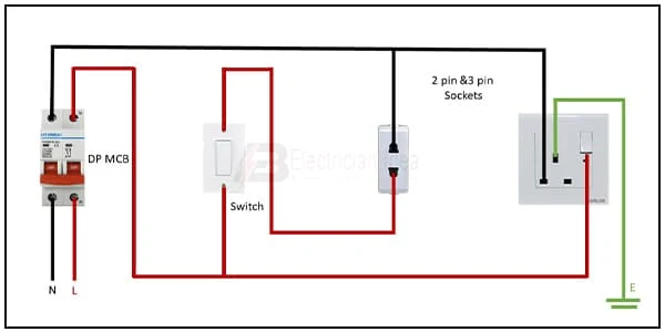
This diagram shows how to make a Socket switch connection. Switch in 2-pin 3-pin socket wiring. In this circuit, we use a DP MCB ( Double Pole Miniature Circuit Breaker ), a switch, and two sockets. Here we need to connect all components like in our diagram. Now this circuit is ready for use. This circuit is very simple and easy to make. If you want to know more about this circuit please check our youtube video below the post.
Diagram of 2-pin socket wiring:
Components Need for this Project:
You can get the components from any of the sites below:
Read Also:
Components used to make the socket switch wiring:
01. DP MCB
 |
| Fig 2: DP MCB |
Double pole MCB can control two wires. This circuit breaker is generally used in single-phase electric lines. Double pole MCB circuit breaker input has two wires supply two wires and an output. In a single-phase line, A double-pole MCB circuit breaker is used to give good production. This circuit breaker is provided through phase and neutral circuit breaker, it is very safe. This circuit breaker is preferred for home appliances. A DP MCB usually trips for 2 reasons 1. Overload 2. Short circuit.
02. Switch
 |
| Fig 3: Switch |
A Single-Pole, Single-Throw (SPST) Switch. It's Got one Output and One Input. The Switch will Either be Closed or Completely Disconnected. SPSTs are Perfect for on-off Switching. They're also a Very Common Form of Momentary Switches. SPST Switches are Commonly Used in a Variety of Electrical Circuits and Applications, Such as Turning on And off Lights, Fans, and Other Appliances. They can Also be Used to Control the Flow of Electricity to Different Parts of a Circuit or to Switch Between Different Circuits Altogether.
03. Socket
 |
| Fig 4: Socket |
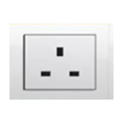
A socket is a type of equipment used in electrical wiring lines that always has an electrical connection. According to the need, it can be supplied to the electrical equipment. In case of electric iron, electric hand drill machine and electric hand grinder etc. two-pin socket with earth terminal is used. Also, three-pin sockets are used for electrical appliances that have a metal body and are likely to be electrified. Eg – Refrigerator, room heater, table heater, hot-plate, electric oven etc.
Thank You for visiting the website. Keep visiting for more Updates.
Frequently Asked Questions
Some devices are double Power supply insulated so the Circuit diagram can use 2 pins safely. Some devices are not and they need 3 pins for safety. 2-pin devices can be connected to either socket, but it will be unsafe to connect 3-pin devices to 2-pin sockets without ground.
The 2-wire switch (Power supply Sourcing Equipment / PSE) is the power supply-providing component of the Project system. It supplies electrical power over a two-wire connection to the connected device.
A 2-pin to 3-pin adapter project system works by allowing a 110-volt item (with the 2-pin plug) to be plugged into the Currenttlou 240-volt Currenttlou outlet (the 3-pin plug socket). Inside the 2-pin to 3-pin adapter, the current flows at the Circuit diagram required level. Some appliances have voltage changers inside them that allow them to use the available current.
The single switch power supply controls a single light (or lighting circuit diagram). 2-Way Switches: A '2-way' switch means there is another switch controlling the same light. These are often used on a staircase, or large room with switches by each door.
Please do not connect more than 1 cable between the 2 switches Circuit diagram because you will create a loop. If you need redundancy you should enable STP on 1820 before connecting the second cable. First, you should check if it will be working.


Post a Comment
Do leave your comments