Single phase Meter connection:
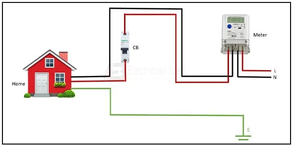
This circuit diagram shows how to Single Phase Meter Connection. Electrical Meter Wiring Diagram. In this circuit, we use a single-phase meter, and a SP MCB ( Single Phase Energy Meter ). First, we need to connect the energy meter to a power generator, then input the power to SP MCB ( Single Pole Miniature Circuit Breaker ). Then connect the power with loads. Now this circuit is ready for use. If you want to know more about this circuit please check our youtube video below the post.
Diagram of single phase meter wiring:
Components Need for this Project:
You can get the components from any of the sites below:
Read Also:
Components used to make the Emergy Meter wiring:
01. Single phase Energy Meter
 |
| Fig 2: Single Phase Energy Meter |
The measuring device with the help of which the electric power or energy of a circuit is measured is called Energy Meter (Energy Meter). Also called a watt-hour or kilowatt-hour meter. For home appliances, we used a single-phase energy meter. The single-phase energy meter is directly connected between the line and the load. Both coils produce their magnetic fields, when the meter is connected to the supply line, and the load. Energy meters are used in homes and in industrial applications where we want to found that how much energy is being consumed by home appliances and electrical equipment.
02. SP MCB
 |
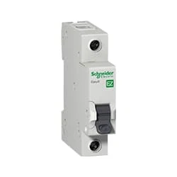
| Fig 3: SP MCB |
MCB SP means single pole it protects only one phase switching. MCB (Miniature Circuit Breaker) Curswitch is the most basic general-purpose switch that you use to control a light or another device from one location. These Switches Have Two Brass-Colored Screw Terminals Connected to the hot Power Source Wires. (MCB) For any Distribution Board, the Protection System Must be Used in The Incomer. Phase and Neutral Single Phase Supply to break. 120-volt circuits, 15-20 amp single pole breaker is typically used.
Thank You for visiting the website. Keep visiting for more Updates.
Frequently Asked Questions
The actual wire connections are quite easy to understand. Three large-gauge stranded wires (two hot wires and one neutral) enter the meter box from a weather head on a metal mast (or from an underground service) and are attached to the corresponding line terminals on the hot and neutral bus bars in the meter box.
ELECTRIC METER is the energy meter or kWh meter and measures the amount of electric energy consumed in kWh for which an electricity bill is paid. It is connected through a cable after the Power supply company fuse on the front or outside wall of the house.
A voltmeter is connected in parallel with a device to measure its voltage Circuit diagrams, while an ammeter is connected in series with a device to measure its current current. At the heart of most analog Project system meters is a galvanometer, an instrument that measures current flow using the movement power supply, or deflection, of a needle.
The standard electric power supply meter is a clock-like device driven by the electricity and moving through it. As the home draws current from the power supply lines, a set of small gears inside the Project system meter move. The number of revolutions is recorded by the dials that you can see on the face of the Project system meter.
It requires only 2 lines: 1 for the power supply to go in and the other is a return path for the current Circuit diagram. These are often called Line 1 and Line 2, or Line 1 and Neutral project system. Current only has one path to travel in a single-phase circuit, such as a control circuit.


Post a Comment
Do leave your comments