Push Relay Connection wiring:
This diagram shows how to make Push Relay Connection Wiring. 8-pin timer relay wiring diagram. In this circuit, we use a DP MCB ( Double Pole Miniature Circuit Breaker ), a push relay, a neutral busbar, two switches, and a CFL light. We need to connect all components like our diagram. Now this circuit is ready for use. If you want to know more about this circuit please check our youtube video below the post.
Diagram of 8-pin timer relay wiring:
Components Need for this Project:
You can get the components from any of the sites below:
- DP MCB [See Buy Click Amazon]
- Busbar [See Buy Click Amazon]
- Pulse Relay [See Buy Click Amazon]
- Light [See Buy Click Amazon]
- Switch [See Buy Click Amazon]
Read Also:
Components used to make the timer wiring:
01. DP MCB
 |
| Fig 2: DP MCB |
Double pole MCB can control two wires. This circuit breaker is generally used in single-phase electric lines. Double pole MCB circuit breaker input has two wires supply two wires and an output. In a single-phase line, A double-pole MCB circuit breaker is used to give good production. This circuit breaker is provided through phase and neutral circuit breaker, it is very safe. This circuit breaker is preferred for home appliances. A DP MCB usually trips for 2 reasons 1. Overload 2. Short circuit.
02. Busbar
 |
| Fig 3: Busbar |
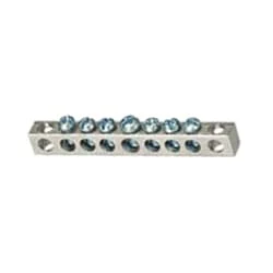
Busbar is a type of power transmission sheet. It is made of copper or brass or aluminum. Busbar is mostly used in factories. We supply the power from the transformer to the busbar. Busbars have electricity. We take the electricity from this busbar to the circuit breaker. The busbar is drilled with a drill machine and the cable is connected with a nut bolt. The advantage of using a busbar is that through it we can provide multiple power connections in multiple places very easily.
03. Pulse Relay
 |
| Fig 4: Pulse Relay |
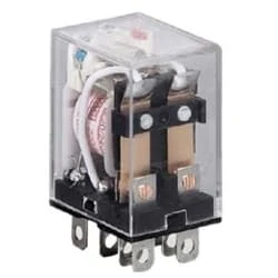
This relay is known as 8 pin relay because it has 8 terminals. When coil power is supplied. A magnetic induction is created due to which the connected sheet of the Com part moves towards the NO part changing to NO-NC. The former NC region loses conductivity and becomes NO. Thus, as long as power is supplied to the coil, the NO and NC positions will remain in the alternating state, and when the power is removed from the coil, it will return to its original position. This is basically how a relay switch works.
04. Light
 |
| Fig 5: Light |
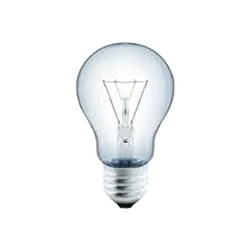
CFLs work in a completely different way from ordinary lamps, they work by using a different process called fluorescence rather than generating light from heat. A typical light bulb wastes 90% of energy and converts only 10% of energy into light, this is where CFL has the biggest advantage. CFL- Curved or conical glass tube filled with argon and a small amount of mercury vapor. The inner wall of the glass is coated with fluorescent material. CFL- It is manufactured using the principle of creating fluorescent light. CFL- Originally white in color but now the construction and use of CFLs producing colored light has become popular.
05. Switch
 |
| Fig 6: Switch |
A Single-Pole, Single-Throw (SPST) Switch. It's Got one Output and One Input. The Switch will Either be Closed or Completely Disconnected. SPSTs are Perfect for on-off Switching. They're also a Very Common Form of Momentary Switches. SPST Switches are Commonly Used in a Variety of Electrical Circuits and Applications, Such as Turning on And off Lights, Fans, and Other Appliances. They can Also be Used to Control the Flow of Electricity to Different Parts of a Circuit or to Switch Between Different Circuits Altogether.
Thank You for visiting the website. Keep visiting for more Updates.
Frequently Asked Questions
8-pin ICs are widely used in many electronic Power supply devices and appliances, such as timers, oscillators, and digital logic circuit diagrams. Molded notch for proper orientation. Easy to insert and remove ICs.
A timer is a small device that Circuit diagram automatically opens and closes an electrical circuit diagram for a specific period of time. In short, we can say that it allows you to program the power supply on/off switching different devices in a simple and straightforward manner Project system.
8-channel Relay module which reduces conventional wiring for triggering relays. Used in conjunction with MODBUS RS485 Master and communication device 4 Baudrate and selections (9600, 19200, 38400, 57600 bps) 7 Slave ID Circuit diagram selection (1 to 7) 8 Relays 10A@230VAC with individual NO-NC with single Change over functionality.
An 8-pin CPU power connector is an optional connector for some CPU circuit diagrams. It has four yellow wires and four black wires, and it plugs into an 8-pin socket on the motherboard. An 8-pin connector can deliver up to 384 watts of power supply, which is twice as much as a 4-pin project system connector.
The Relay is a digital normally open switch that controls a relay capable of switching much higher Circuit diagram voltages and currents than your normal Arduino and boards. When set to LOW, the Project system LED will light up and the relay will close allowing current to flow Circuit diagram. The peak voltage capability Currenttlou is 250V at 10 amps.


Post a Comment
Do leave your comments