Emergency Stop Flash Using Energency Alarm wiring:
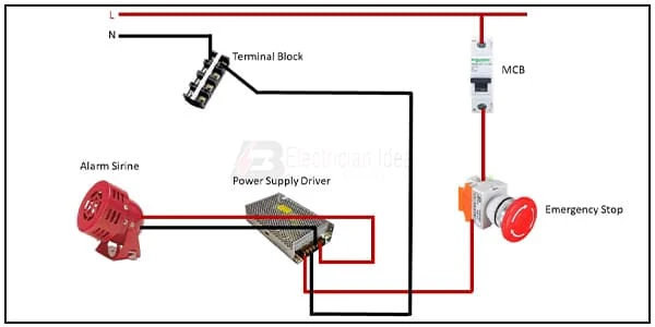
This diagram shows how to make an Emergency Stop Flash Using Emergency Alarm Wiring. In this circuit, we use a terminal block, an SP MCB ( Single Pole Miniature Circuit Breaker ), an alarm siren, a power supply driver, and an emergency stop. This circuit is very simple and easy to make. If you want to know more about this circuit please stay with our website and check our youtube video below the post.
Diagram of Emergency Alarm wiring:
Components Need for this Project:
You can get the components from any of the sites below:
- Power Supply Driver [See Buy Click Amazon]
- Alarm Siren [See Buy Click Amazon]
- Stop Switch [See Buy Click Amazon]
- SP MCB [See Buy Click Amazon]
- Terminal Block [See Buy Click Amazon]
Read Also:
Components used to make the Stop flash Emergency Alarm:
01. Power Supply Driver
 |
| Fig 2: Power Supply Driver |
A Switched-Mode Power Supply (SMPS) is An Electronic Power Supply That Incorporates a Switching Regulator To Convert Electrical Power Efficiently. Like Other Power Supplies, a Switched-Mode Power Supply Transfers Power From a DC or AC Source to DC Loads, Such as a Personal Computer, While Converting Voltage and Current Characteristics. Unlike a linear Power Supply, the Pass Transistor of a Switching-Mode Supply Continually Switches Between low-Dissipation, and full-on and full-off States, which Spends Very Little Time in High-Dissipation Transitions, Which Minimizes Wasted Energy. A hypothetical ideal SMPS (Switched-Mode Power Supply) Dissipates no Power.
02. Alarm Siren
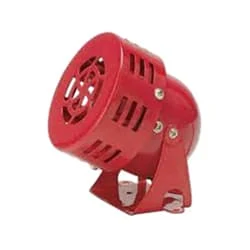 |
| Fig 3: Alarm Siren |
An Alarm Siren is a Loud Noise-Making Device. Civil Defense Alarm Sirens are Mounted in Fixed Locations and Used to Warn of Natural Disasters or Attacks. Alarm Sirens are Used on Emergency Service Vehicles such as Ambulances, Police cars, and Fire Engines. There are two General Types: Mechanical and Electronic. A Civil Defense Siren, also known as an Air-Raid Siren or Tornado Siren, is a Siren Used to Provide an Emergency Population Warning to the General Population of Approaching Danger.
03. Stop Switch
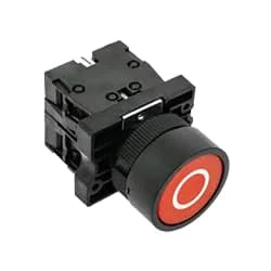 |
| Fig 4: Stop Switch |
Indicates the contacts of switches or automatic actionable devices. Simply put, the push switches, magnetic contactors, and relays that we use in the factory Normally have Close Contact exists. At this moment the switch will be in normally closed condition. Because already he is sitting close. When turned off the contact will open. To make ladder logic you need to understand NC contact. As already explained. The switch contact is already closed in NC. That is enough to understand.
04. SP MCB
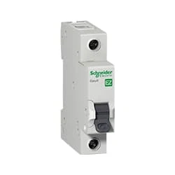 |
| Fig 5: SP MCB |
MCB SP means single pole it protects only one phase switching. MCB (Miniature Circuit Breaker) Curswitch is the most basic general-purpose switch that you use to control a light or another device from one location. These Switches Have Two Brass-Colored Screw Terminals Connected to the hot Power Source Wires. (MCB) For any Distribution Board, the Protection System Must be Used in The Incomer. Phase and Neutral Single Phase Supply to break. 120-volt circuits, 15-20 amp single pole breaker is typically used.
05. Terminal Block
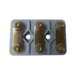 |
| Fig 6: Terminal Block |
A Terminal Block Consists of Modular Housing With An Insulated Body That Secures Two Or More Wires Together. Terminal Blocks—Also Referred to as terminal Connectors, Connection Terminals, or Screw Terminals—are Used in a Wide Array of Applications Where Electrical Systems Need to be Safely Connected. Electrical Terminals are a Class of Electrical Connectors That are Used to Transfer Electrical Current From a Power or Grounding Source to use. Terminals "Terminate" by Crimping or Soldering to Wire or Cable.
Thank You for visiting the website. Keep visiting for more Updates.
Frequently Asked Questions
Emergency stop buttons essentially break an electrical circuit to prevent the power supply from passing through. This causes the machinery to stop functioning immediately. Some emergency stop buttons may connect to a controller if the power supply must be stopped differently.
In addition, the emergency stop button has a direct open circuit diagram action device (forced disconnect device) on the NC contact, but the normal button does not. Because if the contacts are stuck together, the equipment cannot be stopped under hazardous conditions (load).
An Emergency Stop can include but is not limited to, devices such as pull cord-operated switches, foot-operated switches without a mechanical guard and, most commonly, push button-operated switches.
Emergency stop devices provide workers a means of stopping a device during an emergency by pushing a button or pulling a rope to prevent injury to personnel and material loss.
The emergency stop function is a complementary protective measure that is intended to be used in conjunction with other safeguarding measures and protective devices to sufficiently reduce risk.

Post a Comment
Do leave your comments