Electric Cooker using digital timer wiring:
This diagram shows How to make an Electric cooker using digital timer wiring. Electric cooker timer wiring. In this circuit, we use an electric cooker, a power socket, a rotary switch, a digital timer, a DP MCB ( Double Pole Miniature Circuit Breaker ), and a single-phase energy meter. This circuit is very simple and very easy to make. If you want to know more about this circuit please stay with our website and check our youtube video below the post.
Diagram of electric cooker wiring:
Components Need for this Project:
You can get the components from any of the sites below:
- Socket [See Buy Click Amazon]
- DP MCB [See Buy Click Amazon]
- Single phase Energy Meter [See Buy Click Amazon]
- Rotary Switch [See Buy Click Amazon]
- Timer [See Buy Click Amazon]
- Electric Cooker [See Buy Click Amazon]
Read Also:
Components used to make the cooker timer wiring:
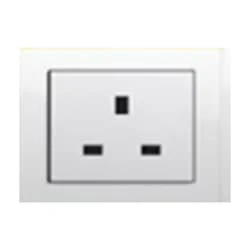
01. Socket
 |
| Fig 2: Socket |
A socket is a type of equipment used in electrical wiring lines that always has an electrical connection. According to the need, it can be supplied to the electrical equipment. In case of electric iron, electric hand drill machine and electric hand grinder etc. two-pin socket with earth terminal is used. Also, three-pin sockets are used for electrical appliances that have a metal body and are likely to be electrified. Eg – Refrigerator, room heater, table heater, hot-plate, electric oven etc.
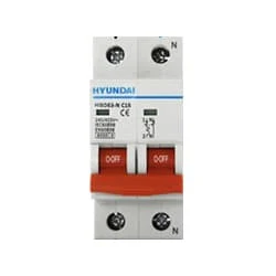
02. DP MCB
 |
| Fig 3: DP MCB |
Double pole MCB can control two wires. This circuit breaker is generally used in single-phase electric lines. Double pole MCB circuit breaker input has two wires supply two wires and an output. In a single-phase line, A double-pole MCB circuit breaker is used to give good production. This circuit breaker is provided through phase and neutral circuit breaker, it is very safe. This circuit breaker is preferred for home appliances. A DP MCB usually trips for 2 reasons 1. Overload 2. Short circuit.
03. Single phase Energy Meter
 |
| Fig 4: Single Phase Energy Meter |
The measuring device with the help of which the electric power or energy of a circuit is measured is called Energy Meter (Energy Meter). Also called a watt-hour or kilowatt-hour meter. For home appliances, we used a single-phase energy meter. The single-phase energy meter is directly connected between the line and the load. Both coils produce their magnetic fields, when the meter is connected to the supply line, and the load. Energy meters are used in homes and in industrial applications where we want to found that how much energy is being consumed by home appliances and electrical equipment.
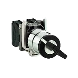
04. Rotary Switch
 |
| Fig 5: Rotary Switch |
Selector Switches Can be Rotated left, Right, or in The Center in Order to Open or Close The Electrical Contacts. The Function of a Selector Switch is To Control Devices as well as Switch Between a Minimum of Two or More Circuits. The perfect Use For a Selector Switch is When Used for Controlling an Output of a Device. Selector Switches Come as a Complete Unit Often listed as a Terminal Block Meaning the Selector Switch is a Complete Block Which Makes it Simple And easy to Install.
05. Timer
 |
| Fig 6: Timer |
Timer is a specialized type of clock used for measuring specific time intervals.An electromechanical cam timer uses a small synchronous AC motor turning a cam against a comb of switch contacts. This type of timer often has a friction clutch between the gear train and the cam, the cam can be turned to reset the time.A simple example of the first type is an hourglass. Working method timers have two main groups: hardware and software timers.Most timers give an indication that the time interval that had been set has expired.
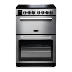
06. Electric cooker
 |
| Fig 7: Electric Cooker |
Kitchen appliances with an electrical motor include electric or induction stoves. It is substantially more effective, secure, and practical than traditional solid-fuel stoves. Since they can complete the same tasks as a typical gas burner in a fraction of the time and just require a rotary switch to operate, electric stoves are quickly gaining favor.
Thank You for visiting the website. Keep visiting for more Updates.
Frequently Asked Questions
With the mounting box fixed in its position above the worktop height and to the side of the cooker, connect the cable running from the consumer unit to the terminals marked “IN” of the cooker's control unit. Brown to the Live terminal, Blue to the power supply Neutral terminal, and Green-and-Yellow to the Earth and terminal.
Installing an electric cooker can be a complex task that requires electrical Circuit diagram knowledge and expertise. While some people may feel confident doing it themselves, it's recommended that you hire a qualified electrician to do the work.
The electrical requirements for single electric ovens can vary depending on the Project system-specific model and local electrical codes. In many cases, single electric ovens do not necessarily power supply need to be hardwired. They can be either hardwired or connected using a suitable power supply cord and plugged into a dedicated electrical outlet.
A cooker is regarded as a piece of fixed Circuit diagram equipment unless it is a small table-mounted type fed from a plug by a flexible cord. Such equipment must be under the control of a local switch, usually in the form of a cooker control unit. This switch may control two cookers, provided both are within 2 m of it.
Yes, an electric cooker can be plugged into a normal socket, but it's important to ensure that the socket and the circuit it's connected to can handle the electrical load required by the cooker.


Post a Comment
Do leave your comments