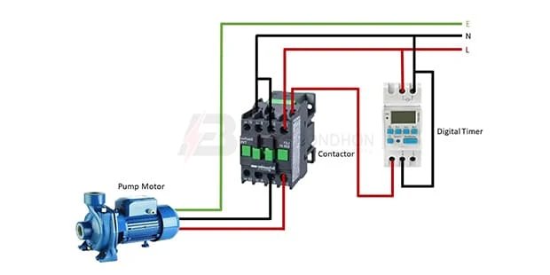
Digital Timer in Pump Motor wiring:
This diagram shows how to make Digital Timer in Pump Motor Wiring. In this circuit, we use a single-phase motor, a magnetic contactor, and a digital timer. First, we need to connect the timer and contactor like in our diagram, then connect the pump motor with the contactor. Now this circuit is ready for use. If you want to know more about this circuit please check our youtube video below the post.
Diagram of timer switch wiring:
Components Need for this Project:
You can get the components from any of the sites below:
- Pump Motor [See Buy Click Amazon]
- Contactor [See Buy Click Amazon]
- Digital Timer [See Buy Click Amazon]
Read Also:
Components used to make the Project_name:
01. Pump Motor
 |
| Fig 2: Pump Motor |
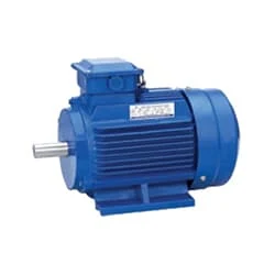
Single-Phase Induction Motor is Very Simple in Construction, Economical, Reliable, and Easy to Repair And Maintain. Due to all these advantages, it is widely used in vacuum cleaners, fans, centrifugal pumps, blowers, washing machines, etc. It can run only by supplying 1 phase current through this motor. The main two parts of this motor are Rotor and Stator. Among them, the rotating part is the Rotor and the stationary part is the Stator. Like all induction motors, a single-phase induction motor consists of two main parts, the stator, and the rotor.
02. Contactor
 |
| Fig 3: Contactor |
A magnetic contactor is an electrical device used for load control, automation, and protection. It is much like a magnetic reel. However, relays are generally used for low power and voltage, on the other hand, when we think of high power, these heavy-duty contractors only come to mind. It basically works by switching the load on and off. It has 3 terminals whose inputs are denoted as L1, L2, L3, and outputs as T1, T2, and T3. The circuit of the load is made in automation mode or protection using auxiliary contacts. It has two types of terminals. 1) Normally Open (NO). 2) Normally Closed (NC)
03. Digital Timer
 |
| Fig 4: Timer |
Timer is a specialized type of clock used for measuring specific time intervals.An electromechanical cam timer uses a small synchronous AC motor turning a cam against a comb of switch contacts. This type of timer often has a friction clutch between the gear train and the cam, the cam can be turned to reset the time.A simple example of the first type is an hourglass. Working method timers have two main groups: hardware and software timers.Most timers give an indication that the time interval that had been set has expired.
Thank You for visiting the website. Keep visiting for more Updates.
Frequently Asked Questions
They are typically connected to an electrical circuit diagram powered via the main supply. Digital timer switches feature timing circuitry diagrams, switching devices, and no moving parts. Such switches can be used to turn lights on and off at times selected by the user.
The mechanical time switch is wired into a circuit diagram much like a small appliance circuit diagram, with an incoming electrical (LINE) cable connected to screw terminals on the switch, and the outgoing the power supply cable connected to LOAD terminals.
Description. Digital timers keep track of the timing; to trigger an action, to start timing once triggered by an action, or both. Some products are programmable while others may be fixed at the set internal time and function.
Mechanical timers use dials and time switches to set the timing. In contrast, digital diagram timers use electronic timers that require no manual input. GEYA offers several models of digital diagram timer switches, each with similar functions.
With timer operation, the Time Switch controls the output according to the set ON or OFF times. With pulse-output operation, the Time Switch outputs a pulse of the specified time width at the set ON time. The power supply was turned ON by a Time Switch.


Post a Comment
Do leave your comments