Changeover Switch Connection:
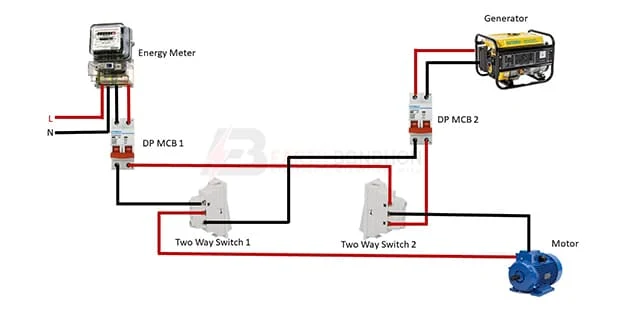
This diagram shows how to make Changeover Switch Connection in 2-way Switch. In this circuit, we use a single-phase energy meter, two DP MCBs ( Double Pole Miniature Circuit Breaker ), two 2-way switches, a power generator, and a single-phase motor. This circuit is very simple and easy to make. If you want to know more about this circuit please stay with our video below the post.
Diagram of 2-way switch for ATS wiring:
Components Need for this Project:
You can get the components from any of the sites below:
- Energy Meter [See Buy Click Amazon]
- DP MCB [See Buy Click Amazon]
- 2-way Switch [See Buy Click Amazon]
- Generator [See Buy Click Amazon]
- Motor [See Buy Click Amazon]
Read Also:
Components used to make the Changeover switch connection:
01. Energy Meter
 |
| Fig 2: Energy Meter |
The measuring device with the help of which the electric power or energy of a circuit is measured is called Energy Meter (Energy Meter). Also called a watt-hour or kilowatt-hour meter. For home appliances, we used a single-phase energy meter. The single-phase energy meter is directly connected between the line and the load. Both coils produce their magnetic fields, when the meter is connected to the supply line, and the load. Energy meters are used in homes and in industrial applications where we want to found that how much energy is being consumed by home appliances and electrical equipment.
02. DP MCB
 |
| Fig 2: DP MCB |
Double pole MCB can control two wires. This circuit breaker is generally used in single-phase electric lines. Double pole MCB circuit breaker input has two wires supply two wires and an output. In a single-phase line, A double-pole MCB circuit breaker is used to give good production. This circuit breaker is provided through phase and neutral circuit breaker, it is very safe. This circuit breaker is preferred for home appliances. A DP MCB usually trips for 2 reasons 1. Overload 2. Short circuit.
03. 2-way Switch
 |
| Fig 4: 2-way Switch |
The two-way switch is a type of multiway switch. Multiway switches have more points and can be controlled in multiple ways simultaneously. The middle connection normally goes to the load and the two side connections act as switches. Again, the opposite is also true if it is used in the lamp connection.It is a type of switch that has three wire connections. And it really has no off or on. Both sides can be turned on or off depending on how you connect one to the other. The two-way switch is a type of multiway switch. Multiway switches have more points and can be controlled in multiple ways simultaneously. Two Way Switch has three wire connection system.
04. Generator
 |
| Fig 5: Generator |
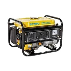
The Power Generator Is a Device That Converts Motive Power (Mechanical Energy) or Fuel-Based Power (Chemical Energy) Into Electric Power for Use in an External Circuit. In Addition to Electromechanical Designs, Photo Voltaic, And Fuel Cell-Powered Generators Utilize Solar Power and Hydrogen-Based Fuels, Respectively, to Generate Electrical Output. The Reverse Conversion of Electrical Energy Into Mechanical Energy is Done by an Electric Motor, And Motors, And Generators Have Many Similarities. Many Motors can be Mechanically Driven to Generate Electricity; Frequently They Make Acceptable Manual Generators.
05. Motor
 |
| Fig 6: Motor |
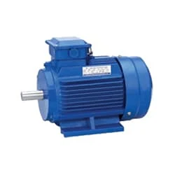
Single-Phase Induction Motor is Very Simple in Construction, Economical, Reliable, and Easy to Repair And Maintain. Due to all these advantages, it is widely used in vacuum cleaners, fans, centrifugal pumps, blowers, washing machines, etc. It can run only by supplying 1 phase current through this motor. The main two parts of this motor are Rotor and Stator. Among them, the rotating part is the Rotor and the stationary part is the Stator. Like all induction motors, a single-phase induction motor consists of two main parts, the stator, and the rotor.
Thank You for visiting the website. Keep visiting for more Updates.
Frequently Asked Questions
In this circuit, we use a power generator, 2 DP MCB ( Double Pole Miniature Circuit Breaker ) a changeover switch, and a single-phase energy meter. First, we need to input power into the energy meter, then input power to DP MCB from the energy meter, and then input power to changeover.
The changeover switches connect the critical loads/ circuits, the main power supply grid, the generator, or an alternate Circuit diagram source. When manually operated, the power flowing to the critical loads/circuit changes from either the main power grid or generator, preventing backfeed into each other.
With a 2-way switch, flicking either switch changes the state of the project system light, regardless of where the other 1 is. You can't have “on” or “off” makers (e.g. writing or red markings) on a 2-way switch, because it can be on or off in either Circuit diagram position.
A 3-way switch is larger than a single pole switch and has 3 screw terminals for wiring power supply connections, plus a ground. 2 of these take traveler wires that go from 1 switch to the current other. For the third terminal, one switch is connected to the hot power supply wire while the other switch is joined to the light.
2 cables enter the switch box: 1 supplying the power supply and one going to the fixture. The neutral wires are spliced, and a black wire connects to each switch Circuit diagram terminal. (Ground wires are not shown).


Post a Comment
Do leave your comments