Automatic Water Level Controller wiring:
This diagram shows how to make Automatic Water Level Controller Wiring. In this circuit, we use a single-phase motor, a water level controller, and two water tanks. First, we need to connect the water level controller then connect the single-phase motor, then connect the overhead tank and underground tank with the water level controller. Now this circuit is ready for use. If you want to know more about this circuit please check the youtube video below the post.
Diagram of water level controller wiring:
Components Need for this Project:
You can get the components from any of the sites below:
Read Also:
Components used to make the water level controller wiring:
01. Water Level Controller
 |
| Fig 2: Water Level Controller |
The water level controller automatically switches the feed pump on and off to ensure the water level inside the boiler. It is mounted next to the steam drum. The performance of the water level controller should be checked regularly, especially the low and high water cut-off tests should be done regularly. The only weakness of a transistor-based circuit is that very little current can pass through the base, resulting in less current flowing through the emitter and collector. In this, the lead burns very weakly and may not be seen in daylight. So we need to arrange to increase the current. We have seen earlier that this can be done using multiple transistors.
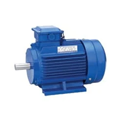
02. Single Phase motor
 |
| Fig 3: Single phase motor |
Single-Phase Induction Motor is Very Simple in Construction, Economical, Reliable, and Easy to Repair And Maintain. Due to all these advantages, it is widely used in vacuum cleaners, fans, centrifugal pumps, blowers, washing machines, etc. It can run only by supplying 1 phase current through this motor. The main two parts of this motor are Rotor and Stator. Among them, the rotating part is the Rotor and the stationary part is the Stator. Like all induction motors, a single-phase induction motor consists of two main parts, the stator, and the rotor.
Thank You for visiting the website. Keep visiting for more Updates.
Frequently Asked Questions
The operation of the water level controller was based on the fact that water conducts electricity. As the water level rises or falls the sensing probes or circuits diagram of the controller detects the same. These signals are used to switch no switch OFF the pump motor as per requirements.
An automatic water level controller is an electronic device that controls the level of the water in a tank. It consists of a sensor that detects the water level in the tank and a control unit that regulates the flow of the water into the tank.
Principle of Water Level Indicator. The working principle of the water level indicator is quite simple. the Water level indicators work by using sensor probes to indicate water levels in a storage tank. These probes send information back to the control panel to trigger an alarm and indicator.
The working principle of the water level sensor was that when it is put into a certain depth in the liquid to be measured, the pressure on the sensor's front surface was converted into the liquid level height. The calculation formula is Ρ=ρ.
1) Check the Fuse at the right side edge of the controller. If it is blown away, replace the fuse. However, it is recommended to get the motor checked for high current by authorized service personnel of the manufacturing company of the motor. (2) The wiring from the controller to the motor should be checked by the electrician.


Post a Comment
Do leave your comments