Automatic Transfer Switch wiring:
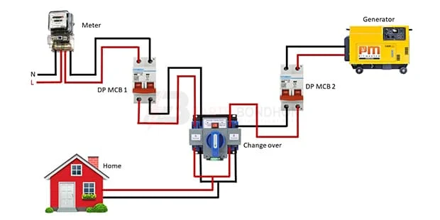
This diagram shows how to make Automatic Transfer Switch Wiring. In this circuit we use a single-phase energy meter, two DP MCBs ( Double Pole Miniature Circuit Breaker ), a power generator, and a changeover switch. First, we need to connect the DP MCB 1 with the meter, then connect the changeover with DP MCB 1. Again connect the power generator with the DP MCB 2, then connect the changeover with DP MCB 2. Now this circuit is ready for use. If you want to know more about this circuit please check our youtube video below the post.
Diagram of ATS wiring:
Components Need for this Project:
You can get the components from any of the sites below:
- Energy Meter [See Buy Click Amazon]
- DP MCB [See Buy Click Amazon]
- Changeover [See Buy Click Amazon]
- Generator [See Buy Click Amazon]
Read Also:
Components used to make the Transfer Switch:
01. Energy Meter
 |
| Fig 2: Energy Meter |
The measuring device with the help of which the electric power or energy of a circuit is measured is called Energy Meter (Energy Meter). Also called a watt-hour or kilowatt-hour meter. For home appliances, we used a single-phase energy meter. The single-phase energy meter is directly connected between the line and the load. Both coils produce their magnetic fields, when the meter is connected to the supply line, and the load. Energy meters are used in homes and in industrial applications where we want to found that how much energy is being consumed by home appliances and electrical equipment.
02. DP MCB
 |
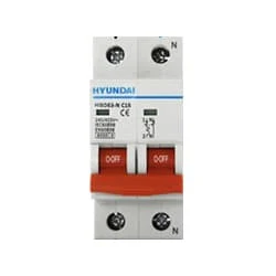
| Fig 3: DP MCB |
Double pole MCB can control two wires. This circuit breaker is generally used in single-phase electric lines. Double pole MCB circuit breaker input has two wires supply two wires and an output. In a single-phase line, A double-pole MCB circuit breaker is used to give good production. This circuit breaker is provided through phase and neutral circuit breaker, it is very safe. This circuit breaker is preferred for home appliances. A DP MCB usually trips for 2 reasons 1. Overload 2. Short circuit.
03. Changeover
 |
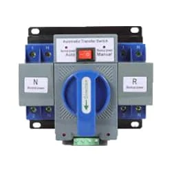
| Fig 4: Changeover |
Changeover is a medium of line transfer used in industry. Now if I make the change over the system automatically then this system is called auto change over the system is called ATS system. From this change over first power supplied from REB or PDB is supplied to the industry to run the machine. Now if for some reason the power supply When stops, the generator is run and the changeover is turned and power is supplied to the machine. Now if this power supply is done manually like this and if it is done manually by any person then it is a manual changeover.
04. Generator
 |
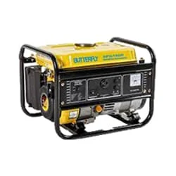
| Fig 5: Generator |
The Power Generator Is a Device That Converts Motive Power (Mechanical Energy) or Fuel-Based Power (Chemical Energy) Into Electric Power for Use in an External Circuit. In Addition to Electromechanical Designs, Photo Voltaic, And Fuel Cell-Powered Generators Utilize Solar Power and Hydrogen-Based Fuels, Respectively, to Generate Electrical Output. The Reverse Conversion of Electrical Energy Into Mechanical Energy is Done by an Electric Motor, And Motors, And Generators Have Many Similarities. Many Motors can be Mechanically Driven to Generate Electricity; Frequently They Make Acceptable Manual Generators.
Thank You for visiting the website. Keep visiting for more Updates.
Frequently Asked Questions
While connected to the Circuit diagram emergency source, the ATS monitors the condition of the current normal source. When acceptable power returns, the transfer switch initiates a transfer from the emergency source to the normal source. After sensing the restoration of an acceptable power supply, an ATS initiates retransfer to the normal source.
The inlet box is hardwired through the power supply wall, indoors to the transfer switch. The switch itself is usually mounted on the Circuit diagram wall near the electrical panel and is hardwired into certain circuit diagrams in the panel. NOTE: Some transfers and switches do not require an inlet box.
How an Automatic Transfer of Funds Works. Typically, customers set up transfers from one financial account to another in advance. These payments can be scheduled to occur Circuit diagram automatically. You can set up regular intervals for these automatic transfers, such as once a week, twice a Power supply month, or every three months or more.
Homes in North America use single-phase 120/240 Volt transfer switches. Many business and commercial applications use three-phase power, 208,480 or 600 volts. Transfer switches come in different sizes. They are typically matched to the size of electrical service you are provided with by the utility company.
There are two types of automatic transfer switches, circuit breakers and contactors. The circuit diagram breaker type has two interlocked circuit breakers, so only 1 breaker can be closed at any time.


Post a Comment
Do leave your comments