Temperature Sensor Circuit fan control Wiring:
A temperature sensor has been used to measure the temperature of the room fan control using Battery 12V. A design Temperature Based Fan Speed Control LM35 Temperature Sensor. The temperature controls the speed of an electric fan according to the requirement & allows dynamic and faster control using Battery 12V.
Diagram of Temperature Sensor circuit fan control wiring:
Components Need for this Project:
You can get the components from any of the sites below:
- 12V DC Fan [See Buy Click Amazon]
- Transistor [See Buy Click Amazon]
- Resistor [See Buy Click Amazon]
- Thermistor [See Buy Click Amazon]
- 12V Battery [See Buy Click Amazon]
Read Also:
Components used to make the Temperature Sensor circuit:
01. 12v DC Fan
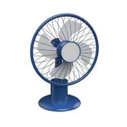 |
| Fig 2: 12v DC Fan |
12V DC cooling fan 2 inches 50mm, The direct current fans, or DC fans, are powered With a potential of Fixed value Such as the voltage Of a battery. It Features maintenance-Free double ball long Service Life, Bearings, Sufficient Heat Dissipation Air Volume, and air pressure. Normally the electricity we use at home is AC and the output of the IPS is AC though it accepts battery (DC) supply during load shedding. If you can't do it yourself, make a bridge rectifier and connect it to the motor (fan) using a 16-volt 100mf electrolytic capacitor. Low fan speed can be caused by an overload of the IPS power you use or a weak capacitor on your fan.
02. Transistor
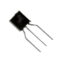 |
| Fig 3: Transistor |
Transistor is a semiconductor device, which is commonly used as an amplifier and electrically controlled switch. Transistors are used as Basic Building Blocks in Computers, Cellular Phones, and all Other Modern Electronics. In terms of the structure of the electronic transistor, the transistor is made by combining two diodes together. For example, if you know that a diode has a p-n junction, adding another p to it will make a p-n-p transistor. It is nothing more than an initial idea. Currently, transistors are not made this way. Transistors are made in a more advanced way.
03. Resistor
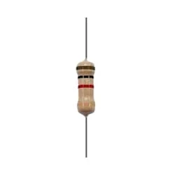 |
| Fig 4: Resistor |
The main function of a resistor is to block the flow of current or cause a voltage drop in an electronic circuit. In short, the function of the register is to prevent the movement of electricity. When we know about electronics, the first name that comes is Resistor. It is basically a common component of electronics. This component is used in every electronic circuit. A resistor is a very familiar component to those who work with electronics. It has a special function. Resistance is denoted by R. Its unit is the ohm (Ω). The following figure shows some resistor symbols that are used in various circuit boards and circuit diagrams.
04. Thermistor
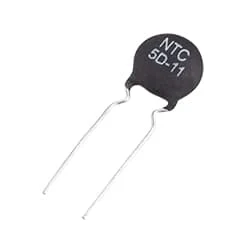 |
| Fig 5: Thermistor |
A Thermistor is a type of Resistor whose Resistance depends on Temperature. A Thermistor is a Combination of Thermal and resistors. It is Usually Used As a Temperature Sensor. It is made of temperature-sensitive material. Thermistors typically operate at temperatures from -55°C to +200°C. A Thermistor is Made of Semiconducting Material ie its Resistance is Between the Conductor and the Insulator. It is made in various forms (beds, rods, discs) by a mixture of various metallic oxides such as manganese, cobalt, copper, iron, and uranium.
05. 12v Battery
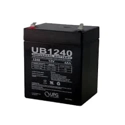 |
| Fig 6: 12v Battery |
A 12-volt Battery is an Irregular Battery used in Specific Electronic Applications. Of all the types of Batteries, the 12-Volt Battery is one That Looks Very Different Depending on its use. It can be Large or small, Heavy or Light. Twelve-volt batteries are commonly used in RV, Boat, and Other Automobiles Systems. From a Technical Perspective, a Battery Uses one or more cells to Allow a Chemical Reaction Creating the flow of Electrons in a Circuit.
Thank You for visiting the website. Keep visiting for more Updates.


Post a Comment
Do leave your comments