Connect Regulator to Switch:
A switching regulator is a circuit diagram that uses a power switch, an inductor, and a diode to transfer energy from input to output line 220v ac. The fan regulator to control is an integral part of electric switchboards to connect 220v ac lines. Control the Fan speed of your fan and adjust it to suit your preferences.
Diagram of Connect Regulator to switch:
Components Need for this Project:
You can get the components from any of the sites below:
- ELCB [See Buy Click Amazon]
- SP MCB [See Buy Click Amazon]
- 2-way Switch [See Buy Click Amazon]
- Fan [See Buy Click Amazon]
- Regulator [See Buy Click Amazon]
Read Also:
Components used to make the regulator to switch:
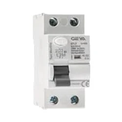
01. ELCB
 |
| Fig 2: ELCB |
An earth-leakage circuit breaker (ELCB) is a safety device used in electrical installations with high Earth impedance to prevent shock.Generally, the current sensing devices termed Residual current Circuit Breaker (RCCB), and voltage detecting devices named Earth Leakage Circuit breaker Earth-Leakage Circuit Breaker (ELCB). For several years, both the voltage and current operated ELCBs were both referred to as ELCB (Earth-Leakage Circuit Breaker) due to their simple name to remember. But the applications of these 2 devices gave growth to the significant mix-up in the electrical industry.
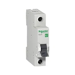
02. SP MCB
 |
| Fig 3: SP MCB |
MCB SP means single pole it protects only one phase switching. MCB (Miniature Circuit Breaker) Curswitch is the most basic general-purpose switch that you use to control a light or another device from one location. These Switches Have Two Brass-Colored Screw Terminals Connected to the hot Power Source Wires. (MCB) For any Distribution Board, the Protection System Must be Used in The Incomer. Phase and Neutral Single Phase Supply to break. 120-volt circuits, 15-20 amp single pole breaker is typically used.
03. 2-way Switch
 |
| Fig 4: 2-way switch |
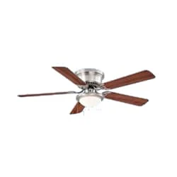
04. Fan
 |
| Fig 5: Fan |
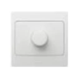
05. Regulator
 |
| Fig 6: Regulator |
Thank You for visiting the website. Keep visiting for more Updates.
Frequently Asked Questions
Using a fan without a regulator can potentially lead to damage if the fan is designed to be used with a regulator. Without a regulator, the fan may operate at a constant speed, which could cause the motor to overheat and potentially lead to damage over time.
Regulators in ceiling fans are used to control and regulate the power supply speed of the fan. Specifically, regulators control fans by controlling the voltage passing through to the fans. These simple but effective devices have been around since the Circuit diagram 1950s and come in many types.
Lastly, but most importantly is the speed regulator. Most of the time, the ceiling fan is in perfect shape but the Circuit diagram regulator, a small round knob placed on the wall switch powering supplies the fan, is broken. As suggested, the speed regulator determines the project system speed at which the fan rotates.
A series connection implies the resistance is in line with the Circuit diagramfan. This reduces the voltage drop across the fan and its speed to your current desired level. The greater the resistance, the higher the voltage drop across it, and that lowers the speed of the fan.
The purpose of the switch is to turn the Circuit diagram fan on and off and on. For example, you can install a ceiling fan that is directly wired to the power supply with no switch. The power supply problem with this is that it will run continuously. A switch simply allows you to control when the fan is on or off.


Post a Comment
Do leave your comments