Day-night Sensor wiring:
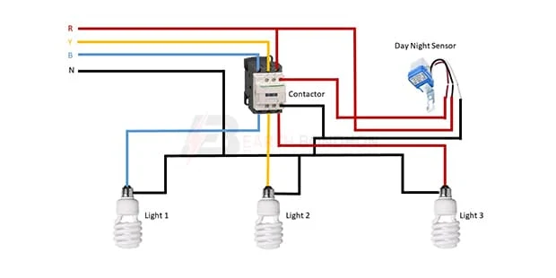
This diagram shows how to make Day Night Sensor wiring. Light Sensor Wiring Diagram. In this circuit, we use a day-night sensor a magnetic contactor and 3 CFL lights. First, we need to input the power connection to the magnetic contactor, then connect the day-night sensor with the contactor. then connect all lights with the sensor and contactor. Now this circuit is ready for use. If you want to know more about this circuit please stay with our website for more details about this diagram please check our youtube video below the post.
Diagram of Light swnsor wiring:
Components Need for this Project:
You can get the components from any of the sites below:
Read Also:
Components used to make the Light Sensor wiring:
01. Contactor
 |
| Fig 2: Contactor |
A magnetic contactor is an electrical device used for load control, automation, and protection. It is much like a magnetic reel. However, relays are generally used for low power and voltage, on the other hand, when we think of high power, these heavy-duty contractors only come to mind. It basically works by switching the load on and off. It has 3 terminals whose inputs are denoted as L1, L2, L3, and outputs as T1, T2, and T3. The circuit of the load is made in automation mode or protection using auxiliary contacts. It has two types of terminals. 1) Normally Open (NO). 2) Normally Closed (NC)
02. Day-night sensor
 |
| Fig 3: Day-night Sensor |
An Automatic Day Night Light Sensor Switch can Switch on Any Electrical Device Automatically When Dark Falls And Switch off in the Morning Automatically. This Night light With an Energy-Efficient LED (Light Emitting Diode) can be Plugged into the Socket and has a light sensor so that the lamp switches on automatically when it gets dark. This is a Photo Technology-Based automatic sensor switch for 220V AC mains, which can be Widely Used in Street Lights, Factories, Gardens, Shops, Etc., and Other Places for Automatic Lighting. Turns ON the Light in the Dark & Turns OFF in The Light.
06. Light
 |
| Fig 4: Light |
CFLs work in a completely different way from ordinary lamps, they work by using a different process called fluorescence rather than generating light from heat. A typical light bulb wastes 90% of energy and converts only 10% of energy into light, this is where CFL has the biggest advantage. CFL- Curved or conical glass tube filled with argon and a small amount of mercury vapor. The inner wall of the glass is coated with fluorescent material. CFL- It is manufactured using the principle of creating fluorescent light. CFL- Originally white in color but now the construction and use of CFLs producing colored light has become popular.
Thank You for visiting the website. Keep visiting for more Updates.
Frequently Asked Questions
Day-night sensors are also power supplies called photocells and allow lights to automatically Circuit diagram come on when the sensor detects a certain level of darkness. The fact that the Project system automatically comes on means that they are an excellent Currenttlou security tool.
Light sensors work by the photoelectric effect. Light can behave as a particle, a Circuit diagram is referred to as a photon. When a photon hits the power supply metal surface of the light sensor, the energy of the light is absorbed by the project system electrons, increasing their kinetic energy and allowing the power supply to be emitted from the material.
As the sensor string extends linearly along with the Circuit diagram moving object, it causes the drum and sensor Circuit diagram shafts to rotate. In order to take displacement or position and measurements, the Currenttlou sensor's body is mounted to a fixed surface and the end of the Circuit diagram flexible cable is connected to the Power supply object in motion.
A light sensor switch allows you control over when your space is lit, with no effort on your part to choose the best time to light your home. Customers love our day-night switch that turns on when dark for added security in their home, particularly when away at work until later in the day or longer on holiday.
Sensor cable is a cable construction Power supply designed for optimal performance of signal/data transmission Circuit diagram from a sensor, project system transducer, or transmitter to a control unit. Pressure, liquid, temperature, and flow are just a few of the measurements that can be taken.


Post a Comment
Do leave your comments