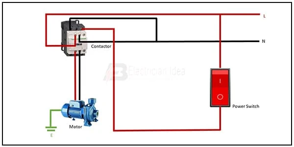
Two way Switch Water Pump wiring:
This diagram shows Two-way Switch Water Pump wiring. In this circuit diagram, we want to clearly describe to you how to connect a water pump with a 2-way switch and a magnetic contactor. In this circuit, we use a magnetic contactor, a water pump, and a 2-way power switch. If you want more clear details about how to connect this circuit diagram please check our youtube video.
Diagram of Two way Switch Water Pump wiring:
Components Need for this Project:
You can get the components from any of the sites below:
- Magnetic Contactor [See Buy Click Amazon]
- Single Phase Motor [See Buy Click Amazon]
- Switch [See Buy Click Amazon]
Read Also:
Components used to make the Two way Switch Water Pump wiring:
01. Magnetic Contactor
 |
| Fig 2: Magnetic Contactor |
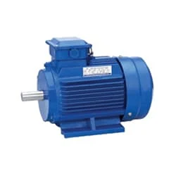
02. Single Phase Motor
 |
| Fig 3: Single Phase Motor |
03. Switch
 |
| Fig 4: Switch |
Thank You for visiting the website. Keep visiting for more Updates.
Frequently Asked Questions
Most 2-way switches have a Common terminal, as well as an L1 and L2 terminal. For 2-way switching, you will need to connect both L1 and L2. For 1-way switching, as you have one less connection, you only need to use the L1 connection. You could leave the L2 connection blank.
The COM terminal of the second switch was connected to one end of the light bulb while the other end of the light bulb was connected to the neutral of the AC Supply. In the default state (as shown in the schematic), the light was off. But when either of the switches was toggled, then the light turned on.
There are several ways to wire a two-way switch. Another way was to run a Live wire to both L1s and a Neutral wire to both L2s, then run a single wire between the 2 Common terminals. The lamp should be on the Neutral wire, between the consumer unit or where the wire splits to meet the switches.
2-way switching means having 2 or more switches in different locations to control 1 lamp. They are wired so that the operation of either switch will control the light(s).
Double pole switches are connected to two separate electric circuit diagrams. They essentially contain two switches that are linked together and could complete the circuit diagram either simultaneously or staggered.


Post a Comment
Do leave your comments