Timer Wiring To Motor Control:
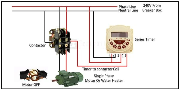
This diagram Shows This Operation is Used to Save Manual Time. This process Starts With The Start Switch Once Pressed, Then the Motor Will Turn ON and OFF Automatically With two Timers. There is a Stop Switch to Stop the Process at any time or in an Emergency Situation. Motor Control Wiring Refers to The Wiring of Various Components of a Motor and Links it to the Controller.
Diagram of Timer Wiring To Motor Control wiring:
Components Need for this Project:
You can get the components from any of the sites below:
- Series Timer [See Buy Click Amazon]
- Terminal Block [See Buy Click Amazon]
- Single Phase Motor [See Buy Click Amazon]
Read Also:
Components used to make the Timer Wiring To Motor Control:
01. Series Timer
 |
| Fig 2: Series Timer |
02. Terminal Block
 |
| Fig 3: Terminal Block |
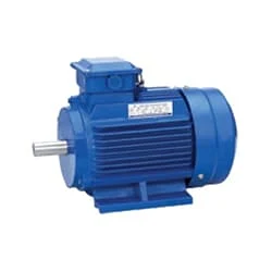
03. Single Phase Motor
 |
| Fig 4: Single Phase Motor |
Thank You for visiting the website. Keep visiting for more Updates
Frequently Asked Questions
The timer control is the looping control used to repeat any task in a given time interval. It is an important control used in Client-side and Server-side programming, as well as in Windows Services. Furthermore, if we want to execute an application after a specific amount of time, we could use the Timer Control.
With timer operation, the Time Switch controls the output according to the set ON or OFF times. With the pulse-output operation, the Time Switch outputs a pulse of the specified time width at the set ON time. The power supply is turned ON by a Time Switch.
The mechanical time switch is wired into a circuit diagram much like a small appliance circuit, with an incoming electrical device (LINE) cable connected to screw terminals on the switch, and the outgoing power supply cable connected to LOAD terminals.
Check the top and side of your outlet timer for a gray or white switch. If the switch is in the “On” or “Off” position, move it to the setting labeled “Timer” instead. That way, anything you plug into the timer shall turn on during the intervals you set.
Here is how a mechanical timer works: When the timer is set, the mechanism inside the timer keeps track of how much time has passed. At predetermined intervals (either preset or adjustable), this internal mechanism would activate and initiate the switch, turning it on and off as programmed.


Post a Comment
Do leave your comments