Three Phase Voltmeter Connection Switch:
This diagram shows how to connect the Three Phase Voltmeter Connection Switch. In this circuit diagram, we just try to describe simply how to connect a Three Phase Voltmeter Connection Switch. This diagram is for the Three Phase Voltmeter Connection Switch. So you can wire your Three Phase Voltmeter Connection Switch office like this diagram very easily. If you want to learn how to connect this circuit clearly you can follow our youtube video link below.
Diagram of Three Phase Voltmeter Connection Switch:
Components Need for this Project:
You can get the components from any of the sites below:
- TP MCB [See Buy Click Amazon]
- Voltmeter [See Buy Click Amazon]
- Selector Switch [See Buy Click Amazon]
- Terminal Block [See Buy Click Amazon]
*Please note: These are affiliate links. I may make a commission if you buy the components through these links. I would appreciate your support in this way!
Read Also:
Components used to make the Three Phase Voltmeter Connection Switch:
01. TP MCB
 |
| Fig 2: TP MCB |
Three wires can be controlled by a triple pole MCB. Triple pole MCB circuit breakers are generally used in three-phase lines. A triple-pole MCB circuit breaker has three wires at its input and three wires at its output. But one can use this circuit breaker in a single-phase line. TP MCB widely used in industries. The reason is that it has three poles. And this TP circuit breaker is used to provide three-phase and three-phase connections. A neutral is not normally used in three-phase lines. But a 4-pole MCB circuit breaker is used if needed.
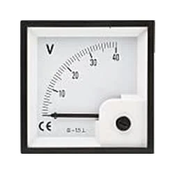
02. Voltmeter
 |
| Fig 3: Voltmeter |
An instrument that measures the potential difference between any two points in a circuit directly in volts is called a voltmeter. To Measure the Potential Difference Between two Points in the Circuit, the Voltmeter Should be Connected in Parallel with those two points. The working common volt meter and ammeter are similar and work on the same principle. Current flows through the coil of the voltmeter at a rate proportional to the voltage and the reading are obtained. The internal resistance of this meter is very high. The coil of a volt meter is made up of many strands of thin wire.
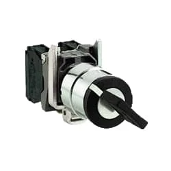
03. Selector Switch
 |
| Fig 4: Selector Switch |
Selector Switches Can be Rotated left, Right, or in The Center in Order to Open or Close The Electrical Contacts. The Function of a Selector Switch is To Control Devices as well as Switch Between a Minimum of Two or More Circuits. The perfect Use For a Selector Switch is When Used for Controlling an Output of a Device. Selector Switches Come as a Complete Unit Often listed as a Terminal Block Meaning the Selector Switch is a Complete Block Which Makes it Simple And easy to Install.
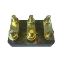
04. Terminal Block
 |
| Fig 5: Terminal Block |
A Terminal Block Consists of Modular Housing With An Insulated Body That Secures Two Or More Wires Together. Terminal Blocks—Also Referred to as terminal Connectors, Connection Terminals, or Screw Terminals—are Used in a Wide Array of Applications Where Electrical Systems Need to be Safely Connected. Electrical Terminals are a Class of Electrical Connectors That are Used to Transfer Electrical Current From a Power or Grounding Source to use. Terminals "Terminate" by Crimping or Soldering to Wire or Cable.
Thank You for visiting the website. Keep visiting for more Updates


Post a Comment
Do leave your comments