Submersible Pump Control Box Connection Wiring | Motor Control Box
Submersible Pump Control Box Connection Wiring:
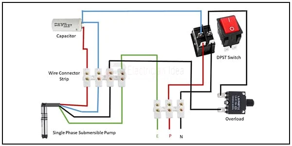
This circuit diagram shows how to connect Submersible Pump Control Box Connection Wiring. In this circuit diagram, we use a submersible pump, a capacitor, a wire connector, a DPST switch, and an overload really. This diagram is very easy to connect. If you want to connect this diagram very easily please check our video in the below article.
Diagram of Pump Control Box Connection wiring:
Components Need for this Project:
You can get the components from any of the sites below:
- Submersible Pump [See Buy Click Amazon]
- Wire Connector [See Buy Click Amazon]
- DPST Switch [See Buy Click Amazon]
- Overload Relay [See Buy Click Amazon]
- Capacitor [See Buy Click Amazon]
*Please note: These are affiliate links. I may make a commission if you buy the components through these links. I would appreciate your support in this way!
$ads={1}
Read Also:
Components used to make the Pump Control Box Connection:
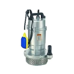
01. Submersible Pump
 |
| Fig 2: Submersible Pump |
All kinds of Submersible Pump Suppliers, and Full Global Submersible Pump Technology Support. Well-known submersible Pump manufacturer, global submersible Pump technology support. Sewage Pump. Screw Pump. Water Pump. Fire Pump. Styles: water pump, centrifugal pump, fire pump, sewage pump.All kinds of Submersible pump suppliers, and full global submersible Pump technology support. global submersible Pump technology support, Well-known submersible Pump manufacturer.
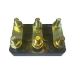
02. Wire Connector
 |
| Fig 3: Wire Connector |
A Terminal Block Consists of Modular Housing With An Insulated Body That Secures Two Or More Wires Together. Terminal Blocks—Also Referred to as terminal Connectors, Connection Terminals, or Screw Terminals—are Used in a Wide Array of Applications Where Electrical Systems Need to be Safely Connected. Electrical Terminals are a Class of Electrical Connectors That are Used to Transfer Electrical Current From a Power or Grounding Source to use. Terminals "Terminate" by Crimping or Soldering to Wire or Cable.
03. DPST Switch
 |
| Fig 4: DPST Switch |
The principle of DPST or Double Pole Single Throw Switch is to control two different circuits simultaneously using a single actuator like a pushbutton, toggle, etc. Both circuits are turned on or off. These switches have four terminals with two outputs and two inputs. It is possible to have different Voltages from different sources Connected to a single Double Pole Single switch. This switch accepts two inputs that can drive two different outputs in a circuit. They are essentially two SPST switches built as one, affecting separate circuits but controlled by the same actuator
04. Overload Relay
 |
| Fig 5: Overload Relay |
Overload relays are often used to protect the motor from excessive current flow. Overload relays are used to protect the motor from overheating. Besides some specific faults such as phase to phase, phase to ground, etc. overload relay provides protection to the motor. A thermal overload relay works on the principle of bimetallic strip electro-thermal characteristics. When the bimetallic heats up, the trip function in the overload relay turns on and disconnects the power supply to the contactor coil, thus tripping the overload relay and breaking the motor current and saving the motor.
05. Capacitor
 |
| Fig 6: Capacitor |
The purpose of the starting capacitor is to provide sufficient torque to start the motor and disconnect from the circuit after the motor reaches a predetermined speed. When voltage is applied to the motor without the start capacitor, the motor will make a humming sound. A start capacitor's capacitance range is between 70 and 120 microfarads. The Start Capacitor Increases The Motor Starting Torque and Allows The Motor to Cycle and run Faster. The Start Capacitor is Designed in Such a Way That it is Used for a Short Time. They cannot stay strong for long.
Thank You for visiting the website. Keep visiting for more Updates
$ads={2}
Frequently Asked Questions
How is the submersible pump connected?
Submersible Motors are supplied with a three-core PVC insulated flat cable of length three meters. The free end of the three-core cable of the motor needs to be connected to the power supply cable from the control panel. As this joint was always nearly submerged in water the joint needs to be waterproof.
How many wires does a submersible pump have?
This week we'll be talking about the difference between 2 and 3-wire submersible well pumps. 1st, both types feature a ground wire which shouldn't be counted. 2 wire pumps will have two black wires and a green wire. 3 wire pumps have black, red, yellow, and green wire.
How do you control pump output?
Another method of controlling pump flow was to use the pump with a variable speed drive which in turn changes the flow of the pump. A 3rd method for controlling flow from a pump was to throttle the discharge by opening and closing a valve at the exit of the pump.
What type of wire is submersible?
Common types of submersible pump cables on the market were twisted-pair copper cables, flat cables, round cables, and heavy-duty cables. The basic difference between flat or round submersible pump cables is the most important thing you need to know about the submersible pump cables.
What voltage is a submersible pump?
In North America, the small ones (1/3-hp, 1/2-hp, 3/4-hp) are usually 120-volts AC. Larger ones are 240-volts AC. Much larger ones (over 5 to 10 hp) were 3-phase (240, 277 and 460, etc). Most everywhere else, all pumps (like all electric motors) were 240.


Post a Comment
Do leave your comments