Solar Panel System Connection Diagram:
This Diagram Shows Solar Panels Are Similar to Batteries In That They Have Two Terminals Positive And Negative. A Series Connection is Made by Connecting The Positive Terminal of One Panel to The Negative Terminal of Another. Connecting at Least Two Solar Panels in This Manner Becomes a PV Source Circuit. In the Series Connection, the Voltages of all Solar Panels are Summed up and the Current is Maintained the Same for all Panels. The Set of Solar Panels Connected in a Series is Known as a String.
Diagram of Solar Panel System Connection wiring:
 |
| Fig 1: Solar Panel System Connection Diagram |
Components Need for this Project:
You can get the components from any of the sites below:
- Solar Panel [See Buy Click Amazon]
- Charge Controller [See Buy Click Amazon]
- Overload Breaker [See Buy Click Amazon]
- Changeover Switch [See Buy Click Amazon]
- 12V Battery [See Buy Click Amazon]
- Wiring Terminal [See Buy Click Amazon]
- Inverter [See Buy Click Amazon]
*Please note: These are affiliate links. I may make a commission if you buy the components through these links. I would appreciate your support in this way!
Read Also:
Components used to make the Solar Panel System Connection Diagram :
01. Solar Panel
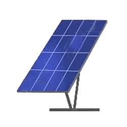 |
| Fig 2: Solar Panel |
Photovoltaic solar panels can generate electricity directly from sunlight. Photovoltaic (PV) modules are connected assemblies of photovoltaic solar cells available in a package of various voltages and wattages, but not direct sunlight. And the sun also does not transmit electricity directly to the earth. Sends light and heat. It has to convert our electricity in different ways. We get heat energy from the sun very easily. Instead, it transmits light and heat.
02. Charge Controller
 |
| Fig 3: Charge Controller |
The function of a solar charge controller is to charge the battery by regulating the voltage and current coming from the solar. That is, reduce the voltage slightly so that the battery cell is not damaged due to high voltage. It's called a controller rather than a charger because it's so smart. Automatically provides proper power to the battery according to over voltage, over the current, short circuit, and battery temperature. There are two types of charge controllers. PWM and MPPT, PWM is relatively cheaper but has lower efficiency. On the other hand, good quality MPPTs are very efficient and offer maximum safety to the battery.
03. Overload Breaker
 |
| Fig 4: Overload Breaker |
Overload relays are often used to protect the motor from excessive current flow. Overload relays are used to protect the motor from overheating. Besides some specific faults such as phase to phase, phase to ground, etc. overload relay provides protection to the motor. A thermal overload relay works on the principle of bimetallic strip electro-thermal characteristics. When the bimetallic heats up, the trip function in the overload relay turns on and disconnects the power supply to the contactor coil, thus tripping the overload relay and breaking the motor current and saving the motor.
04. Changeover Switch
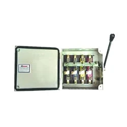 |
| Fig 5: Changeover Switch |
Change-Over Switch A single switching system used to operate one of the electrical systems in the absence of power from two sources (generator and PDB) is called a change over switch. Another is the PDB or Palli Vidyut Samity line made from generators or inverters. When the PDB/Rural power line is on, your company's generator line is off. Again when the PDB line goes off your company's generator line will come on again. The switching system to control these two types of electrical systems is called an automatic change-over switching system.
05. 12V Battery
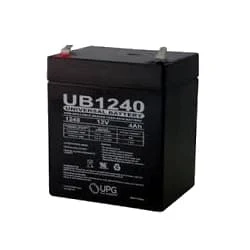 |
| Fig 6: 12V Battery |
A 12-volt Battery is an Irregular Battery used in Specific Electronic Applications. Of all the types of Batteries, the 12-Volt Battery is one That Looks Very Different Depending on its use. It can be Large or small, Heavy or Light. Twelve-volt batteries are commonly used in RV, Boat, and Other Automobiles Systems. From a Technical Perspective, a Battery Uses one or more cells to Allow a Chemical Reaction Creating the flow of Electrons in a Circuit.
06. Wiring Terminal/Terminal Block
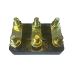 |
| Fig 7: Wiring Terminal/Terminal Block |
A Terminal Block Consists of Modular Housing With An Insulated Body That Secures Two Or More Wires Together. Terminal Blocks Also Referred to as terminal Connectors, Connection Terminals, or Screw Terminalsare Used in a Wide Array of Applications Where Electrical Systems Need to be Safely Connected. Electrical Terminals are a Class of Electrical Connectors That are Used to Transfer Electrical Current From a Power or Grounding Source to use. Terminals "Terminate" by Crimping or Soldering to Wire or Cable.
07. Inverter
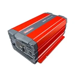 |
| Fig 8: Inveter |
An inverter is an electrical device that converts DC current into alternating current (AC). AC can be operated at any voltage and frequency system with suitable transformers, switches, and control circuits. Most electrical appliances run on AC (Alternative Current). Nowadays inverter is a very common device that is used to change the voltage in any type of machine or to control the speed of the induction motor. For example, the power supply in our country is 50 Hz, and the speed of the motor will also be fixed at this fixed Hz. In such cases inverter is used to drive the motor slowly or strongly.
Thank You for visiting the website. Keep visiting for more Updates


Post a Comment
Do leave your comments