Single-Phase Submersible Pump Motor | submersible starter connection
Single-Phase Submersible Pump Motor Wiring:
This Diagram Shows A Submersible Pump (or electric submersible pump) is a Device That Has a Hermetically Sealed Motor Close-Coupled to The Pump Body. The whole assembly is Submerged in the Fluid to be Pumped. A Submersible Pump Pushes Water to the Surface by Converting Rotary Energy into kinetic energy into pressure energy. This is done by The Water Being Pulled into The Pump: First in The Intake, Where The Rotation of The Impeller Pushes The Water Through The Diffuser.
Diagram of Single-Phase Submersible Pump Motor wiring:
 |
| Fig 1: Single-Phase Submersible Pump Motor Wiring |
Components Need for this Project:
You can get the components from any of the sites below:
- SP MCB [See Buy Click Amazon]
- Ammeter [See Buy Click Amazon]
- Voltmeter [See Buy Click Amazon]
- Push Switch [See Buy Click Amazon]
- Starting Capacitor [See Buy Click Amazon]
- Running Capacitor [See Buy Click Amazon]
- Submersibile Pump [See Buy Click Amazon]
*Please note: These are affiliate links. I may make a commission if you buy the components through these links. I would appreciate your support in this way!
$ads={1}Read Also:
Components used to make the Single-Phase Submersible Pump Motor:
01. SP MCB
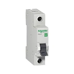 |
| Fig 2: SP MCB |
MCB SP means single pole it protects only one phase switching. MCB (Miniature Circuit Breaker) Curswitch is the most basic general-purpose switch that you use to control a light or another device from one location. These Switches Have Two Brass-Colored Screw Terminals Connected to the hot Power Source Wires. (MCB) For any Distribution Board, the Protection System Must be Used in The Incomer. Phase and Neutral Single Phase Supply to break. 120-volt circuits, 15-20 amp single pole breaker is typically used.
02. Ammeter
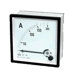 |
| Fig 3: Ammeter |
The Ammeter (Abbreviation of Ampere Meter) is a Measuring Instrument used to find the Strength of the Current Flowing Around an Electrical Circuit when Connected in Series with the part of the Circuit Being Measured. For Direct Measurement, The Ammeter is Connected in Series With the Circuit in Which The Current is to be Measured. An Ammeter’s Current Sensitivity is Determined by the Amount of Electric Current Required by the coil of the Meter to Produce the Required FSD Movement of the Pointer.
03. Voltmeter
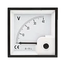 |
| Fig 4: Voltmeter |
An instrument that measures the potential difference between any two points in a circuit directly in volts is called a voltmeter. To Measure the Potential Difference Between two Points in the Circuit, the Voltmeter Should be Connected in Parallel with those two points. The working common volt meter and ammeter are similar and work on the same principle. Current flows through the coil of the voltmeter at a rate proportional to the voltage and the reading are obtained. The internal resistance of this meter is very high. The coil of a volt meter is made up of many strands of thin wire.
04. Push Switch
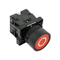 |
| Fig 5: Push Switch |
Indicates the contacts of switches or automatic actionable devices. Simply put, the push switches, magnetic contactors, and relays that we use in the factory Normally have Close Contact exists. At this moment the switch will be in normally closed condition. Because already he is sitting close. When turned off the contact will open. To make ladder logic you need to understand NC contact. As already explained. The switch contact is already closed in NC. That is enough to understand.
05. Starting Capacitor
 |
| Fig 6: Starting Capacitor |
The purpose of the starting capacitor is to provide sufficient torque to start the motor and disconnect from the circuit after the motor reaches a predetermined speed. When voltage is applied to the motor without the start capacitor, the motor will make a humming sound. A start capacitor's capacitance range is between 70 and 120 microfarads. The Start Capacitor Increases The Motor Starting Torque and Allows The Motor to Cycle and run Faster. The Start Capacitor is Designed in Such a Way That it is Used for a Short Time. They cannot stay strong for long.
06. Running Capacitor
 |
| Fig 7: Running Capacitor |
A Run Capacitor is Used in Single-Phase Motors to Maintain a Running Torque on an Auxiliary Coil While The Motor is Toaded. These Capacitors Are Considered Continuous Duty While The Motor is Powered And Will Remain in The Circuit While The Starts Capacitor Drops out. The Run Capacitor, Also Sometimes Called an “A/C Capacitor,” Uses Its Stored Energy to Turn or Run The fan Motor. Without The Run Capacitor, The Fan Cannot Turn. Run Capacitors Are Also Rated by Voltage Classification. The Voltage Classifications are 370V and 440V.
07. Submersibile Pump
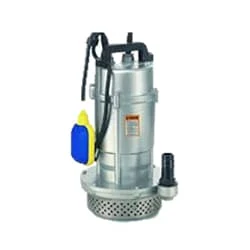 |
| Fig 8: Submersibile pump |
All kinds of Submersible Pump Suppliers, and Full Global Submersible Pump Technology Support. Well-known submersible Pump manufacturer, global submersible Pump technology support. Sewage Pump. Screw Pump. Water Pump. Fire Pump. Styles: water pump, centrifugal pump, fire pump, sewage pump.All kinds of Submersible pump suppliers, and full global submersible Pump technology support. global submersible Pump technology support, Well-known submersible Pump manufacturer.
Thank You for visiting the website. Keep visiting for more Updates
$ads={2}
Frequently Asked Questions
What is the current of a 1 hp single-phase submersible motor?
However, as a general guideline, a 1 HP submersible pump operating at 120 v typically draws around 10 amps, while at the 240 volts it would draw around 5 amps. It's important to consult the manufacturer's specifications for the exact amperage draw of the particular pump model. Single phase at 220 v, and if PF 0.8.
Can a submersible pump run on single-phase?
the Single Phase Submersible Water Pumps: Best Water Pumping Solutions for Homes. Single-phase pumps were commonly used in household applications and run on a single-phase power supply. These could start easily and do not need a strong starting torque.
What is the single-phase submersible pump?
Single-phase pumps were primarily used in cases when the pump was going to be turned on and off multiple times during the day. The single-phase pumps also find extensive usage in remote locations where electricity is not easily available from the electrical device grid.
What is the maximum HP of the single-phase motor?
It contains 2 wires (one hot wire and one neutral wire) and uses a single alternating voltage. Since it only generates an alternate field, it needs the capacitor for startup. Single-phase motors can provide a power supply of up to 10 hp. However, they were typically small in size and offered limited torque capacities.
How to run the single-phase motor at low voltage?
In the low-voltage configuration, the 2 coils of each phase are connected in parallel with each other so that the lower value of power supply voltage is shared equally between the coils and rated current flow is drawn through each winding.


Post a Comment
Do leave your comments