Single Phase Auto Reverse Forward Motor Control:
This Diagram Shows A forward/reverse magnetic motor starter is constructed by two regular contractors and installed with a mechanical interlock that prevents both coils from pulling in simultaneously. The Direction of Rotation of a Single-Phase Capacitor run Induction Motor is Reversed by Changing the Direction of the Rotating Magnetic field Produced by the Main and Starter Winding or Auxiliary Winding.
Diagram of Single Phase Auto Reverse Forward Motor Control wiring:
Components Need for this Project:
You can get the components from any of the sites below:
- Magnetic Contactor [See Buy Click Amazon]
- 8-Pin Timer [See Buy Click Amazon]
- SP Circuit Breaker [See Buy Click Amazon]
Read Also:
Components used to make the Single Phase Auto Reverse Forward Motor Control :
01. Magnetic Contactor
 |
| Fig 2: Magnetic Contactor |
02. 8-Pin Timer
 |
| Fig 3: 8-Pin Timer |
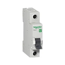
03. Single Pole Circuit Breaker
 |
| Fig 4: Single Pole Circuit Breaker |
Thank You for visiting the website. Keep visiting for more Updates
Frequently Asked Questions
Once started, the single-phase induction motor will happily run in either direction. To reverse it, we need to change the direction of the rotating magnetic field produced by the running and starter windings. This could be accomplished by reversing the polarity of the starter winding.
Your DC motor could be configured to turn in either direction by simply inverting the polarity of the applied voltage. The change in the flow of current flow switches the direction of the spinning force and causes the motor's shaft to begin turning in the opposite direction.
If a motor is to be driven in 2 directions, then it will require a Forward / Reverse motor starter, which has two three-pole horsepower-rated contactors rather than just one as in the conventional starter. Each of the two different motor starters supplies the motor with a different phase rotation.
To control the direction of the motor, the pins in and in two must be set to opposite values. If in1 is HIGH and in2 is LOW, the motor will spin one way, if, on the other hand, in1 is LOW and in two HIGH then the motor will spin in the opposite direction.
By the energization of the Forward contactor coil in the control circuit diagram, the Forward contactor in the power circuit diagram got actuated which makes the motor run in the forward (clockwise) direction.


Post a Comment
Do leave your comments