Series parallel Electrical Testing Board | Testing Board Series and Parallel

Series parallel Electrical Testing Board | Testing Board Series and Parallel

Series parallel Electrical Testing Board:

This diagram shows a series of parallel electrical testing boards. In this circuit diagram, we use a 2-way switch light and a 3-pin socket. First, we need to input the phase line to the 2-way switch and then from the switch to the socket and light. At last, we need to connect the neutral wire to the light like in this circuit diagram. If you want more clear details about this diagram please check our youtube video at the below post.

Diagram of Series parallel Electrical Testing Board wiring:

Components Need for this Project:

You can get the components from any of the sites below:

  1. 2-Way Switch [See Buy Click Amazon]
  2. Light [See Buy Click Amazon]
  3. 3-Pin Socket [See Buy Click Amazon]
*Please note: These are affiliate links. I may make a commission if you buy the components through these links. I would appreciate your support in this way!

$ads={1}

Read Also:

Components used to make the Series parallel Electrical Testing Board:

01. 2-Way Switch

2-Way Switch
Fig 2: 2-Way Switch
The two-way switch is a type of multiway switch. Multiway switches have more points and can be controlled in multiple ways simultaneously. The middle connection normally goes to the load and the two side connections act as switches. Again, the opposite is also true if it is used in the lamp connection.It is a type of switch that has three wire connections. And it really has no off or on. Both sides can be turned on or off depending on how you connect one to the other. The two-way switch is a type of multiway switch. Multiway switches have more points and can be controlled in multiple ways simultaneously. Two Way Switch has three wire connection system.


02. Light

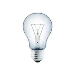
Light
Fig 3: Light
CFLs work in a completely different way from ordinary lamps, they work by using a different process called fluorescence rather than generating light from heat. A typical light bulb wastes 90% of energy and converts only 10% of energy into light, this is where CFL has the biggest advantage. CFL- Curved or conical glass tube filled with argon and a small amount of mercury vapor. The inner wall of the glass is coated with fluorescent material. CFL- It is manufactured using the principle of creating fluorescent light. CFL- Originally white in color but now the construction and use of CFLs producing colored light has become popular.

03. 3-Pin Socket

3-Pin Socket
Fig 4: 3-Pin Socket
A socket is a type of equipment used in electrical wiring lines that always has an electrical connection. According to the need, it can be supplied to the electrical equipment. In case of electric iron, electric hand drill machine and electric hand grinder etc. two-pin socket with earth terminal is used. Also, three-pin sockets are used for electrical appliances that have a metal body and are likely to be electrified. Eg – Refrigerator, room heater, table heater, hot-plate, electric oven etc.

Thank You for visiting the website. Keep visiting for more Updates


$ads={2}

Frequently Asked Questions

Which is better series or parallel?

Answer and Explanation: In a parallel circuit diagram, every appliance is connected to the battery and the supply. Also, there is the same voltage across each of the appliances. A parallel circuit diagram is better than a series circuit because in case of any failure only the appliance connecting the faulty pathway will stop working.

What is an example of a series-parallel circuit?

If a wire joins the battery to 1 bulb, to the next bulb, to the next bulb, to the next bulb, and then back to the battery in 1 continuous loop the bulbs are said to be in the series. If each bulb the wired to the battery in a separate loop the bulbs are said to be in parallel.

What is the series-parallel method?

The basic idea of the series-parallel method is to successively use the equivalent of the resistance rules for series or parallel resistors in a sequence of steps. First, we replace all the resistors in series with their equivalent of the resistances. This step usually leaves some of the resistors in parallel.

Which is more powerful series or parallel?

In a series circuit, the total power supply dissipated is generally less than in a parallel circuit. This is because, in a series circuit diagram, the same current flows through each component, so the total power supply dissipated is divided among the components.

What is the disadvantage of parallel over series?

The major disadvantage of parallel circuits diagram as compared to series circuits is that the power remains at the same voltage as the voltage of a single power supply source. Other disadvantages include the splits of an energy source across the entire circuit diagram, and lower resistance parallel circuits cannot be effectively used.

Post a Comment

Do leave your comments

Previous Post Next Post

Advertisements

Advertisements

Blogging Experiment
Electronic Experiment Subscribe our Youtube Channel
Subscribe